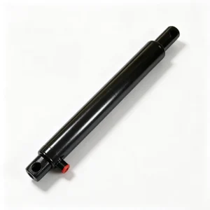
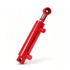
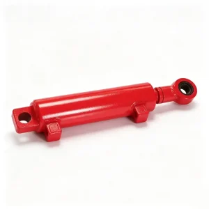
Corn Harvester Steering Cylinder YM4P.83K.05 – 40mm Bore, 190mm Stroke

Double-acting rear-axle steering cylinder with a 1.32:1 push/pull ratio for symmetric left-right steering feel. Rated 10,000+ full lock-to-lock cycles; ≤2 cc/min leakage prevents passive drift on cross-slopes. Steel-reinforced double-lip wiper handles rear-axle mud and stone-chip exposure. OEM-fit for YM4P platform — custom stroke and geometry review available. Get a quote.

الوصف

YM4P.83K.05 · Corn Harvester Series

Corn Harvester Steering Cylinder

Double-acting, high-cycle steering actuator for the rear-axle power steering system of 4-row self-propelled corn harvesters — engineered for symmetrical response, zero drift, and 10,000+ cycle seasonal durability.

Bore 40 mm
Rod 25 mm
Stroke 190 mm
C/C 387 mm
Part No. YM4P.83K.05
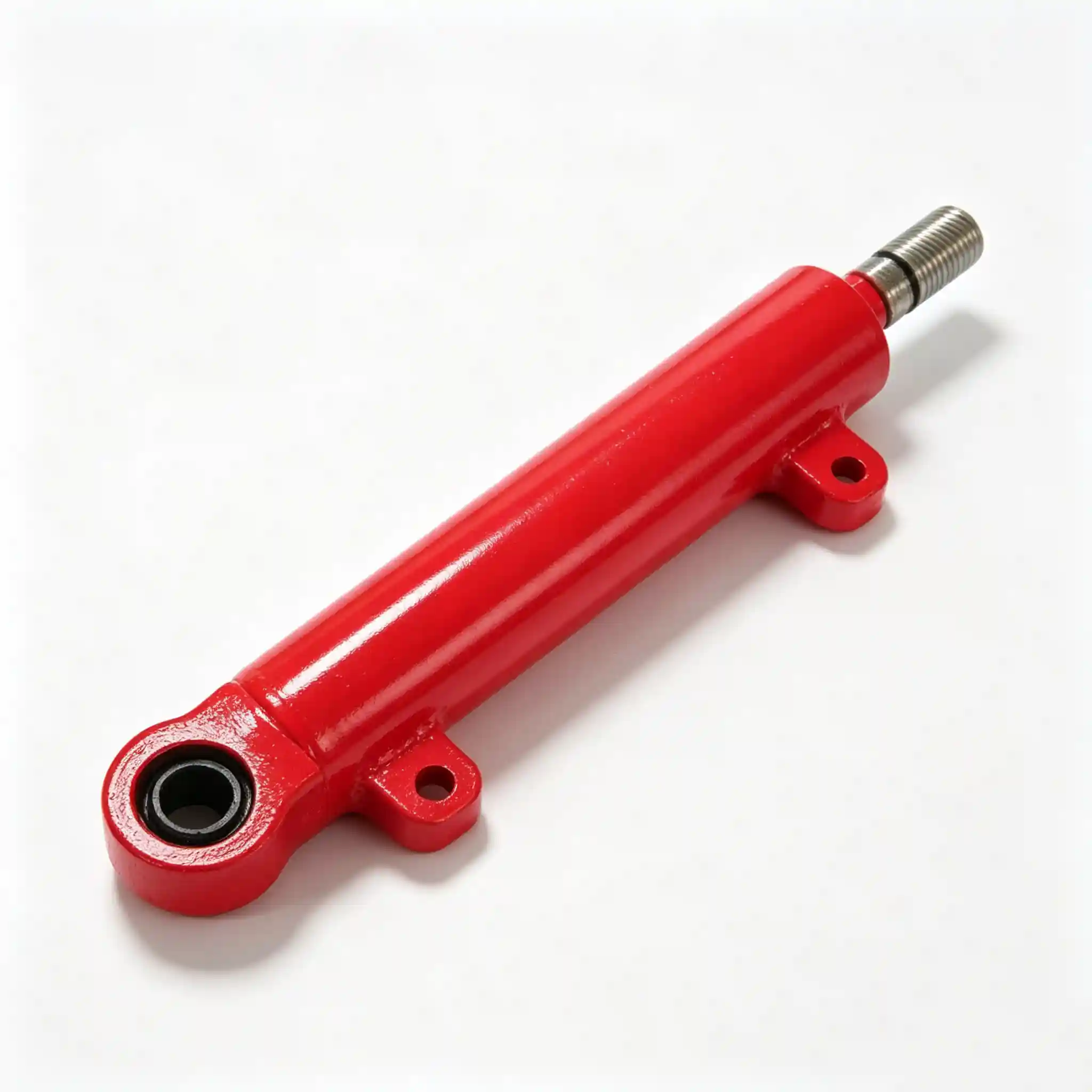
YM4P.83K.05 Corn Harvester Steering Cylinder — 40mm bore 25mm rod 190mm stroke double-acting hydraulic steering actuator for self-propelled corn harvester

Full Specification at a Glance

Bore Diameter

40 mm

Push force ≈ 20.1 kN @ 160 bar — sufficient for full rear-axle steering load

Rod Diameter

25 mm

Rod/bore ratio 0.625 — near-symmetric push/pull for equal left/right steering response

Stroke

190 mm

Full lock-to-lock rear axle travel on 4-row platform geometry

Mounting Distance

387 mm

C/C retracted. Extended: 577 mm. Governs rear axle bracket geometry.

Rated Pressure

160 bar

Continuous working pressure — shared steering/hydraulic circuit

Surge Pressure

220 bar

Kerb-strike and hard-lock shock rated — proof tested per unit

Cycle Rating

10,000+

Full lock-to-lock cycles before seal service — lab endurance verified

Internal Leakage

≤ 2 cc/min

Tightest spec in this cylinder family — steering drift is a safety issue

Rod Chrome

25–30 µm

Hard chrome HV 800+. Rear axle position — mudpack and stone chip exposure

Mounting Style

Clevis × 2

Ø18 mm pin bore both ends — smaller pin reflects lower bending moment on short-stroke steering linkage

Push Force (Left Lock)

20.1 kN

F = 160 bar × π/4 × 40²

Pull Force (Right Lock)

15.2 kN

F = 160 bar × π/4 × (40²−25²)

Force Asymmetry

1.32 : 1

The tightest push/pull ratio in this cylinder family — essential for equal left and right steering feel

Lock-to-Lock Time

≈ 1.4 s

At 8 L/min dedicated steering circuit flow — responsive without being twitchy at field speeds

The YM4P.83K.05 corn harvester steering cylinder is the only cylinder in this six-unit set that is directly coupled to operator safety. Every other cylinder on this machine controls an agricultural function — header height, grain discharge, chopper gap. This one controls where the machine goes. A sticking engagement cylinder costs time; a compromised steering cylinder on a 10-tonne self-propelled harvester travelling a headland at 8 km/h costs significantly more.

That framing is not alarmist — it is the engineering justification for why the steering cylinder carries the tightest internal leakage specification (≤ 2 cc/min), the highest cycle-endurance rating (10,000+ full lock-to-lock), and the most conservative surge pressure rating (220 bar) of any cylinder on this harvester. It is also why the rod diameter of 25 mm — giving a push/pull force ratio of just 1.32:1 — is selected specifically to minimise left-right steering force asymmetry rather than to maximise push force, as would be the design priority on a lift or dump cylinder.

For OEM engineers and parts procurement managers: this cylinder is not interchangeable with a generic 40/25 agricultural cylinder. The sealing system, cycle rating, and leakage specification are steering-duty specific. Understanding why each parameter is set as it is — and what degrades when it is not met — is the basis for making the correct sourcing decision.

Self-propelled corn harvester navigating headland turn — steering cylinder controls rear axle direction on every field pass and headland manoeuvre

Every headland turn and field-pass correction runs through the steering cylinder — cycle count accumulates faster than any other actuator on the machine

Hydraulic Steering Cylinder for Self-Propelled Corn Harvester — Engineering Rationale Behind Each Specification

Q

Why is the push/pull ratio only 1.32:1 — far lower than the chopper cylinder’s 4.53:1 or the header lift’s 4.54:1?

Steering cylinders are the one application in agricultural hydraulics where push/pull force asymmetry translates directly into a driver experience problem. If the cylinder generates 20.1 kN turning left but only 8.7 kN turning right, the operator must apply noticeably different input force on the steering valve to achieve the same lock speed in each direction. On a joystick-steered or manually piloted harvester, this asymmetry is immediately felt and creates operator fatigue, imprecise headland alignment, and — on slopes — a tendency to drift toward the high-force direction when the operator relaxes input.

The 25 mm rod on a 40 mm bore gives an annular area of 755 mm² versus a full bore area of 1,257 mm² — a ratio of 0.60. This produces 15.2 kN retract against 20.1 kN extend: a 1.32:1 ratio that is close enough to symmetric for the driver to feel no meaningful difference between left and right lock. Every millimetre added to the rod diameter beyond 25 mm would worsen this balance. The specification is a deliberate steering-feel decision, not a default.

Q

Why does the steering cylinder accumulate more cycles per season than any other actuator on the machine?

Consider the operating pattern. A dump cylinder cycles once every 15–25 minutes of harvesting — perhaps 30–40 times per day. The header lift cylinder moves 10–20 times per hour as the operator raises and lowers for headland turns. The steering cylinder, by contrast, moves continuously: every row correction, every headland pivot, every obstacle avoidance input, every adjustment to cross-slope drift. On a 10-hour harvest day with 200 m rows and 90° headland turns, a conservative estimate yields 400–600 partial stroke steering inputs and 80–120 full or near-full lock manoeuvres.

Over a 30-day season, this accumulates to 12,000–18,000 steering events — ranging from minor directional corrections (5–20% stroke) to full lock-to-lock turns. The 10,000+ full-cycle laboratory endurance rating corresponds to this real-world seasonal load. A cylinder with a lower cycle rating — or, more commonly, one that meets cycle count targets only in a clean laboratory environment without the road grit, mud, and chaff contamination of rear-axle duty — will begin showing rod seal weep within 1–2 seasons.

Q

Internal leakage is specified at ≤ 2 cc/min — tighter than any other cylinder in this set. What goes wrong at higher leakage rates?

On a lift or dump cylinder, internal piston seal leakage manifests as slow position drift — annoying, but correctable by the operator. On a steering cylinder, internal bypass has a qualitatively different consequence: under sustained side loading — crosswind, side slope, or road camber — the cylinder will slowly drift toward the low-pressure side as oil bypasses the piston seal from the high-pressure port to the low-pressure port. The machine steers itself toward the ditch.

Quantifying the threshold: at 5 cc/min internal leakage (the spec limit for the grain tank lift cylinder), a steering cylinder under 80 bar sustained side load drifts approximately 2.5 mm/min. Over 4 minutes of straight-ahead harvesting without active operator correction, that is 10 mm of cylinder travel — roughly 3–4° of rear axle angular error, enough to walk the machine off-row by 0.3–0.5 m per field length. At ≤ 2 cc/min, that error drops to under 1.5° over the same period — within normal operator correction frequency. The ≤ 2 cc/min limit is the engineering threshold below which passive drift is invisible to an attentive operator.

Q

What makes rear-axle steering the most hostile contamination environment for a cylinder on this machine?

The steering cylinder lives in the most contaminated position on the harvester. Unlike the header, grain tank, or chopper cylinders — which are in the machine’s upper or mid structure — the rear-axle steering cylinder is at ground level, directly exposed to mud spray from the rear tyres, stone chip from turns on headland tracks, water from stream crossings, and the compacted soil paste that accumulates on rear axle components after a rain delay.

This exposure pattern drives three specification decisions: (1) the double-lip wiper with a reinforced steel exclusion lip rather than a standard single-lip — the outer lip physically shears mud plugs from the rod on every retract stroke; (2) chrome depth of 25–30 µm rather than 18–20 µm typical of sheltered-position cylinders — thicker chrome survives stone chip impacts without exposing the steel substrate; (3) full external paint system with 80 µm minimum DFT and zinc phosphate conversion coating rather than bare phosphate — the rear axle environment routinely fails 240-hour salt spray test specimens that would pass comfortably in a mid-machine position.

Q

The surge pressure is 220 bar — what events generate surges in a steering cylinder that would not occur in a lift or dump cylinder?

Two events are specific to steering duty. First: hard-lock impact. When the rear axle reaches full steering lock against the mechanical stop and the operator continues to hold steering input — a routine occurrence, particularly during tight headland turns — the full circuit pressure is applied to a stationary cylinder against a rigid stop. On a machine with a pressure-compensated steering circuit, this saturates at relief valve setting; on a fixed-displacement circuit, the pressure spike can briefly exceed 200 bar before the relief opens. The 220 bar surge rating ensures the cylinder tube and end-cap welds are not the weakest element in this event. Second: obstacle impact on the rear axle. Driving over a large stone or buried root at field speed transmits an impulsive lateral force through the rear steering linkage into the cylinder in the retract direction. This generates a rod-side pressure spike that bypasses the circuit relief valve on the timescale of the impact. The 220 bar rating covers the estimated peak of this event for the platform weight class this machine falls into.

Agricultural Power Steering Cylinder — Construction and Material Standards for Rear-Axle Duty

Cylinder Tube

E355 cold-drawn seamless, 40 mm bore × 7 mm wall. Honed Ra ≤ 0.4 µm. External: zinc phosphate conversion coat + two-coat PU topcoat, 80 µm minimum DFT. Salt-spray tested 500+ hours. All external machined faces passivated before painting.

قضيب الكروم

Ck45 steel, ground Ra ≤ 0.2 µm. Hard chrome 25–30 µm, HV 800+. Post-chrome ground to h6. Stone-chip resistance is a primary selection criterion at 25 mm diameter — chrome adhesion spec requires ≥ 35 N/mm² bond strength, verified by scratch test on production batches.

Wiper / Seal Pack

Double-lip wiper: reinforced steel exclusion outer lip + PU inner lip. Inner rod seal: dual-lip PU rated to 10,000 full-stroke cycles. Piston: quad-ring PU + PTFE backup. Bronze guide ring with widened contact face for lateral load management in side-loaded steering duty.

End Fixings

Clevis both ends, Ø18 mm pin bore. Sintered bronze self-lubricating bush — no grease nipple required on standard spec (grease-nipple option available). Clevis eyes machined to H7 for pin fit. Locking: castellated gland nut with tab washer.

QC Protocol

Hydrostatic proof 220 bar × 60 s per unit. Full-stroke × 10 cycles (double the standard protocol — steering duty). Leakage both ports: ≤ 2 cc/min verified at rated pressure. Dimensional audit: C/C, stroke, pin bore. Records retained per batch.

Corn field at harvest — corn harvester steering cylinder must perform precisely across every row, turn and headland throughout the entire season

Straight-row tracking and precise headland turning both depend on the steering cylinder maintaining zero-drift position hold between active steering inputs

Fitment Verification — Critical Dimensions for Replacement and Cross-Reference

Steering cylinder replacement is higher stakes than other cylinders on this machine: an incorrect C/C or stroke dimension changes the maximum steering angle, which directly affects minimum turning radius and headland manoeuvrability. Verify all four dimensions before ordering.

C/C Retracted

387 mm

Primary bracket dimension. A 10 mm error here changes the straight-ahead axle geometry.

Stroke

190 mm

Determines full steering lock angle. Short-stroke substitute reduces turning circle.

Pin Bore

Ø18 mm

Both ends. Smaller than other cylinders in this set — confirm pin diameter on machine.

Rod Diameter

25 mm

Do not substitute larger rod — changes force asymmetry and steering feel. See above.

Port Thread

BSP G3/8″

Steering circuit typically uses smaller port sizes than lift circuits. Confirm hose fittings before ordering.

OEM Corn Harvester Hydraulic Steering Actuator — Custom Specifications for Platform Integrators

Steering geometry varies more between machine platforms than any other hydraulic function — axle pivot positions, tie-rod lengths, and kingpin offsets all interact with cylinder stroke and C/C to produce the target steering angle. Custom configurations are supported across the following parameters:

  • Stroke: 150–250 mm. Specify target full-lock steering angle and axle geometry — our engineering team back-calculates the required cylinder stroke from your linkage dimensions if required.
  • Mounting distance (C/C): Adjustable to specification. Straight-ahead axle geometry must be confirmed against the new C/C before production sign-off.
  • Rod diameter: Standard 25 mm for balanced steering feel. 28 mm available where platform geometry requires increased retract force — provided with updated force asymmetry calculation and steering-feel impact note.
  • Port standard: BSP G3/8″, SAE ORB #6, NPT 3/8″. Specify to match steering circuit hose standard — field adapters on steering circuits introduce a potential leak point at the most safety-critical hydraulic connection on the machine.
  • End-of-stroke cushion: Available for platforms where the cylinder reaches full lock at high steering-input speed — reduces impact loading on the mechanical stop and extends cylinder end-cap fatigue life.
  • Seal material: Standard PU/PTFE for mineral oil; FKM for biodegradable HETG circuits increasingly mandated in EU and Canadian agricultural markets.
  • OEM identification: Part number engraving and private-label documentation at MOQ ≥ 50 pcs — lower volume custom configurations supplied with standard Ever-Power identification unless otherwise agreed.

All custom steering cylinder configurations supplied with 2D dimensional drawing, steering-geometry compatibility note, and STEP file for bracket design review — before production confirmation. Standard lead time 7–15 business days ex-works; custom 20–30 business days. Seal kit catalogued and stocked separately for all configurations.

Complete YM4P Corn Harvester Cylinder Series — All Six Actuators at a Glance

A full-machine hydraulic cylinder set — all six components available from one supplier, with consistent manufacturing standards, matched documentation, and consolidated procurement logistics.

Part No.FunctionBoreRodStrokeC/C
YM4P.83.03Engagement Cylinder40 mm22 mm110 mm348 mm
YM4P.83.02bHeader Lift Cylinder56 mm50 mm300 mm660 mm
YM4P.83.06aGrain Tank Lift Cylinder63 mm40 mm1,425 mm1,780 mm
YM4P.83.01Chopper Cylinder56 mm50 mm130 mm390 mm
YM4P.83.04bHopper Dump Cylinder63 mm40 mm695 mm1,200 mm
YM4P.83K.05Steering Cylinder This Page40 mm25 mm190 mm387 mm

Source the Full Set or a Single Unit

Request OEM Pricing, Steering Geometry Review, or Complete YM4P Cylinder Set Documentation

All six YM4P corn harvester cylinders are available from a single source — consolidated documentation, matched manufacturing standards, and one point of contact for the complete hydraulic cylinder bill of materials. OEM and distributor enquiries receive engineering drawings and material certifications as standard.