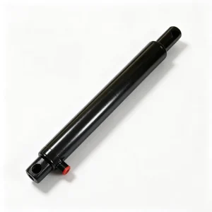
Beschreibung
Agricultural Hydraulic Cylinders › Grain Handling › Grain Tank Lifting Cylinder
Model HCYY11112016
Grain Tank Lifting Cylinder
for Combine Harvesters
A purpose-built grain tank lifting cylinder engineered for the full-stroke, high-load demands of combine harvester grain tank elevation — where 607 mm of uninterrupted travel and a 65 mm bore deliver consistent lift force through 16.7 MPa working pressure cycles, season after season.
Rod Φ35 mm
Stroke 607 mm
Install 823 mm
16.7 MPa WP
Weight 18 kg
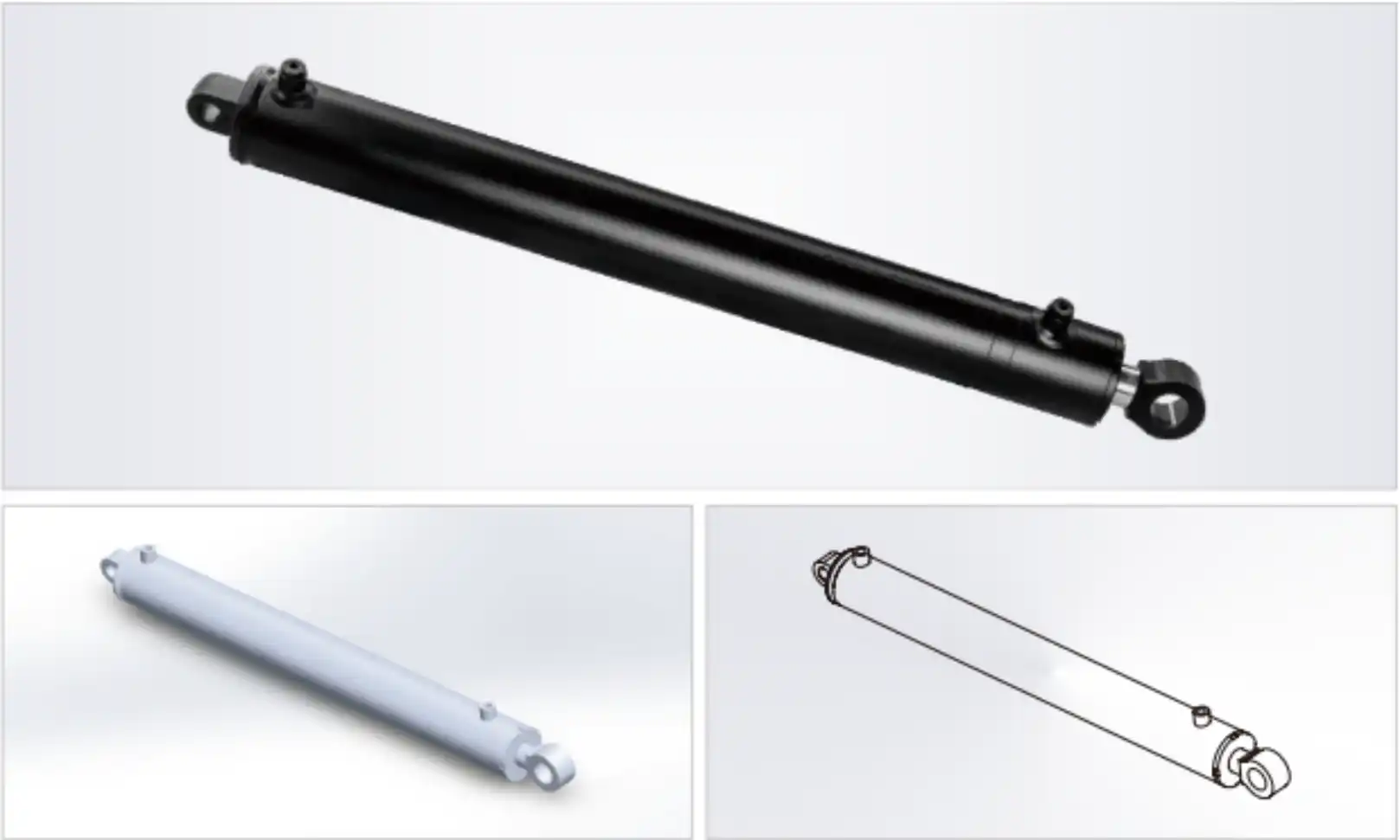
Product Overview
Why Grain Tank Lifting Cylinder Specification Directly Determines Harvest Throughput — and What Fails When It Is Wrong
The Harvest-Window Problem
A combine harvester’s grain tank operates in a cycle of fill, travel, and unload that repeats dozens of times per day during peak harvest. Every time the grain tank tilts for unloading into a chase wagon or grain cart, the lifting cylinder must extend its full stroke under the weight of the loaded tank — which on a mid-range combine can reach 4,000–8,000 kg of grain plus tank structure. A cylinder that cannot sustain rated pressure across the full 607 mm stroke will fail to hold the tank at maximum tilt angle, causing incomplete unloading, grain spillage, and the kind of downtime that costs significantly during a narrow harvest window.
The Load-Holding Requirement
Unlike excavator cylinders that complete thousands of push-pull cycles per hour, the grain tank lifting cylinder must hold a static load at full extension for extended periods — 60–120 seconds per unloading cycle — while the grain flows out by gravity. Any internal piston seal bypass allows the tank to settle during unloading, reducing the effective tilt angle and leaving residual grain in the tank bottom. Over a full harvest season, this residual accumulates as moisture-trapping contamination that promotes fungal growth in the tank lining. Piston seal integrity across the full bore of 65 mm is therefore a crop-quality specification, not just a mechanical one.
The HCYY11112016 grain tank lifting cylinder is engineered specifically for this duty profile. Its 65 mm bore, 35 mm rod, and 607 mm stroke are not generic selections — they reflect the force, reach, and structural requirements of combine harvester grain tank geometry in the medium-to-large machine class. The 16.7 MPa working pressure rating and 24.5 MPa maximum withstand pressure provide a 46% pressure safety margin above working conditions, giving the hydraulic system headroom to manage pump pressure spikes during engagement of the tank tilt function without risk of seal extrusion or barrel deformation.
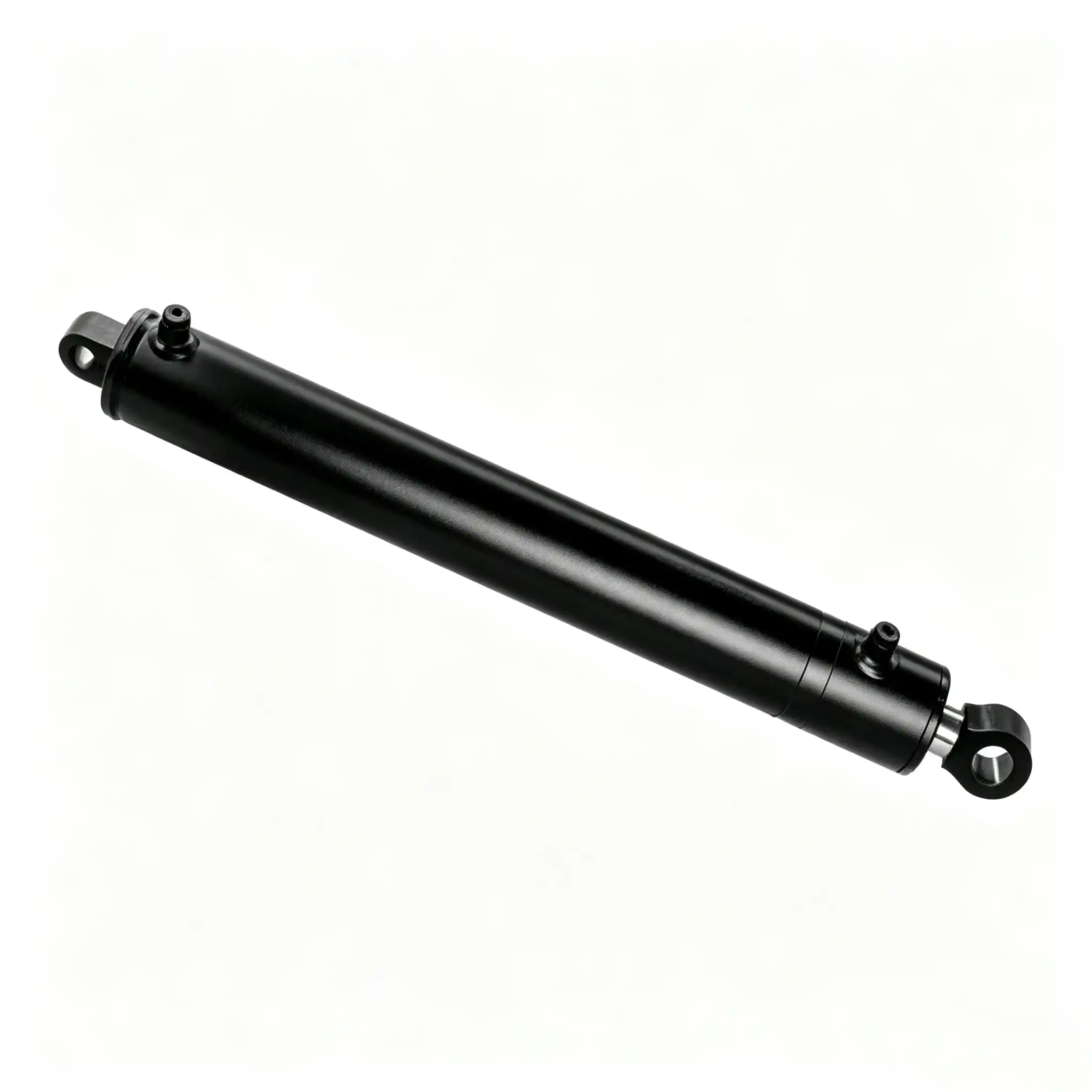
HCYY11112016 — 607 mm stroke grain tank lifting cylinder shown with end-cap and clevis hardware
Technical Specifications
HCYY11112016 Grain Tank Lifting Cylinder 65mm Bore, 607mm Stroke — Parameter Rationale for Agricultural OEM Procurement
| Parameter | Value | Agricultural Significance |
|---|---|---|
| Cylinder Model | HCYY11112016 | OEM part number for direct identification in combine harvester service documentation and parts ordering systems |
| Bore Diameter | Φ65 mm | Piston area 33.2 cm². At 16.7 MPa working pressure, push force ≈ 55.4 kN — sufficient to elevate a loaded grain tank through the full angular range against gravity and friction loads at the tank pivot bearings |
| Rod Diameter | Φ35 mm | Rod cross-section area 9.6 cm². Pull force ≈ 39.1 kN for tank lowering. Rod slenderness ratio at 607 mm extension is within Euler buckling safety limits for the compressive load of the tank return movement under gravity assist |
| Stroke | 607 mm | Controls the angular tilt range of the grain tank from closed (transport) to fully open (unloading) position. At typical tank pivot arm lengths, 607 mm stroke generates 35–45° of tank rotation — the range required for complete gravitational grain flow to the tank discharge point |
| Installation Distance | 823 mm | Pin-to-pin retracted length. Must match the combine harvester’s tank frame pivot spacing within ±2 mm. A mismatch prevents the tank from reaching its closed position, leaving residual gap at the tank seal that allows rain and chaff ingress during field transport |
| Working Pressure | 16.7 MPa | Standard combine harvester hydraulic system operating pressure. Cylinder is rated for sustained operation at this pressure across the full stroke during loaded tank elevation without seal degradation |
| Max Withstand Pressure | 24.5 MPa | 46% safety margin above working pressure. Accommodates hydraulic pump pressure spikes during function engagement, relief valve hunting, and the momentary pressure excursions generated when the tank contacts its full-open stop under momentum |
| Weight | 18 kg | Complete cylinder assembly including end-caps and mounting hardware. Within the payload allowance of standard combine harvester hydraulic mounting frames without structural reinforcement |
Lift Force
55.4 kN
@ 16.7 MPa · Φ65 mm
Lower Force
39.1 kN
@ 16.7 MPa · Φ35 mm rod
Pressure Reserve
+46%
24.5 MPa burst vs 16.7 MPa WP
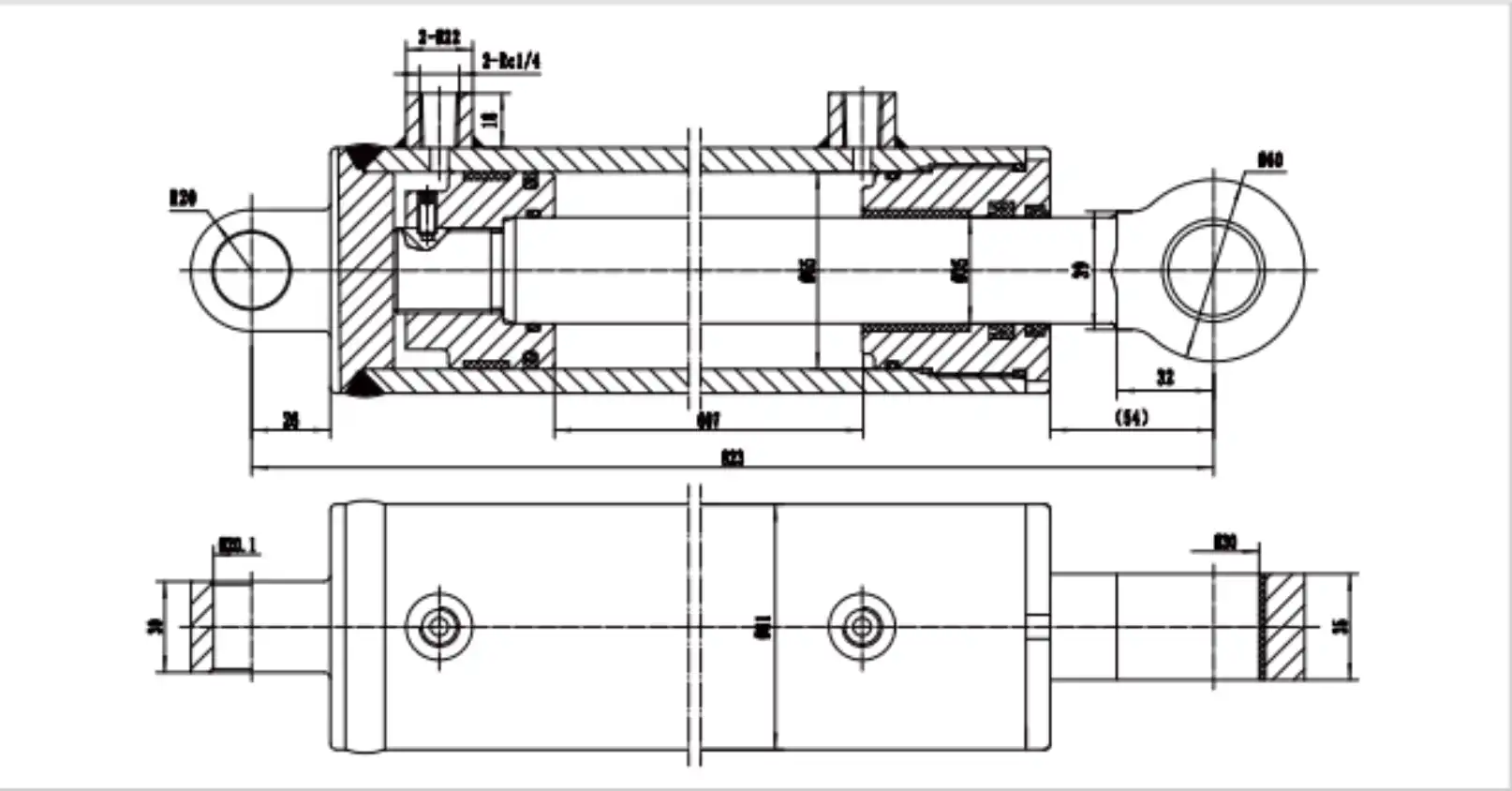
HCYY11112016 dimensional drawing — full technical drawing available on request for OEM and distributor accounts
Manufacturing & Seal Engineering
Hard Chrome Rod, Agricultural-Grade Sealing, and Structural Weld Integrity — Why Harvest-Season Reliability Starts at the Manufacturing Stage
Induction-Hardened, Chrome-Plated Rod
The 35 mm rod is manufactured from 45# medium-carbon steel, induction-hardened to HRC 54–58 at a case depth of 1.5–2.5 mm. The core remains at HRC 28–32, preserving the ductility needed to absorb bending loads from tank misalignment at the clevis pins. A 25–40 μm hard chrome layer is applied to HV 900–1,000 surface hardness and ground to Ra 0.2–0.4 μm. In combine harvester environments, the rod is exposed to chaff dust, fertiliser residue, and humidity cycling between field and storage — conditions that attack unprotected steel surfaces rapidly. The chrome layer provides corrosion resistance against these agricultural-specific chemical exposures that standard industrial chrome specifications do not always address.
Static Load-Holding Piston Seal
The piston seal on a grain tank lifting cylinder must perform a function distinct from dynamic cycling applications: it must hold zero bypass across the full 65 mm bore diameter for extended static periods under full load. The step-cut PTFE or polyurethane U-cup piston seal used in the HCYY11112016 is selected for its self-energising contact geometry — hydraulic pressure in the cylinder bore increases the seal lip’s contact force against the barrel bore wall, maintaining tight bypass closure precisely under the high static pressure conditions of a loaded grain tank. This is the sealing property that prevents the loaded tank from settling during the 60–120 second gravity unloading cycle, ensuring complete grain discharge on every unloading event.
Agricultural Contamination Wiper Seal
Combine harvesters operate in environments with elevated airborne particulate loads — grain dust, chaff fines, and straw fragments that settle on every exposed surface including the cylinder rod. The dual-lip polyurethane wiper seal at the rod gland is specified for agricultural particulate exclusion rather than general industrial standards. The outer lip scrapes coarse chaff and grain dust from the rod on each retraction stroke; the inner lip captures fine dust that passes the outer lip. Between the two lips, an accumulation cavity prevents the combined particulate load from reaching the primary rod seal in a single stroke. Maintaining a clean interface at the primary seal is the variable that most directly determines whether the cylinder reaches the end of the harvest season without requiring a reseal.
- Barrel construction: Cold-drawn seamless steel tube with consistent wall thickness and inclusion-free microstructure. The 65 mm bore barrel wall is dimensioned for the hoop stress at 24.5 MPa maximum withstand pressure with a structural safety factor above 2.5.
- End-cap welds: Full-penetration welding with post-weld stress relief, reducing heat-affected zone residual tensile stress from the as-welded 250–350 MPa range to below 100 MPa — extending fatigue life against the static pressure cycling of seasonal harvest use.
- Clevis pin bores: Machined to H7 tolerance for interference-free pin engagement without the angular play that would impose bending on the rod during tank elevation. Pin bore concentricity is verified before assembly to exclude mounting misalignment from the manufactured cylinder.
- Oil compatibility: All seals are rated for mineral hydraulic oil ISO VG 46 and ISO VG 68 — the two most common combine harvester hydraulic fluid specifications — across the operating temperature range of -20°C to +80°C encountered in temperate and subtropical harvest environments.
Force & Application Analysis
Combine Harvester Grain Tank Unloading: How the 65mm Bore and 607mm Stroke Work Together Under Seasonal Agricultural Loads
Grain Load Distribution and Cylinder Force Demand
A medium-class combine harvester grain tank with a 9,000-litre capacity filled with wheat at approximately 780 kg/m³ bulk density carries approximately 7,000 kg of grain. The cylinder’s mechanical task is to elevate this load through the tank’s tilt arc against gravity. The effective moment arm of the grain mass changes continuously as the tank tilts — it is greatest at the beginning of the tilt cycle (tank horizontal, grain mass fully offset from the pivot) and reduces as the tank approaches vertical and grain flows toward the discharge point. The cylinder’s 55.4 kN push force at 16.7 MPa system pressure is calculated for the maximum moment condition at the initial stage of tank tilt, where the full grain mass acts at its maximum effective arm. As the tilt progresses and grain flows out, the remaining load decreases and the required cylinder force drops proportionally — the cylinder’s force margin increases as unloading proceeds, providing a self-reinforcing safety buffer against any grain bridging or flow restriction event.
Why 607mm Stroke Matters for Complete Unloading
The grain tank’s tilt angle at full cylinder extension determines whether complete gravitational unloading is achievable. At less than 30° of tank rotation, the angle of repose of moist grain (typically 28–35° for wheat and 25–30° for corn) means that a significant portion of the grain mass will not self-flow to the discharge auger — the operator must wait for the flowing grain to uncover the stuck portion before complete discharge. The 607 mm stroke is matched to the pivot arm geometry of the target machine class to produce 38–45° of tank rotation at full extension — reliably above the angle of repose for all common grain crops, including high-moisture grain at harvest that has a higher effective angle of repose than dry stored grain. A shorter-stroke replacement cylinder that produces only 32–34° of maximum rotation would leave a measurable residual grain volume in the tank bottom on every unloading event.
Seasonal Duty Cycle and Service Life Expectations
A combine harvester in a temperate climate operates through a harvest season of 60–90 days for all crops combined, with the grain tank cycling 15–25 times per day during active harvest. This produces 900–2,250 full-stroke lift cycles per season. Unlike earthmoving equipment where a hydraulic cylinder may reach 10,000 cycles per week, the grain tank cylinder operates in a low-frequency, high-static-load profile — where seal performance under sustained static pressure and rod surface protection against off-season corrosion during storage determine service life. With proper off-season storage practices (cylinder in a clean, retracted position with a light oil coating on any exposed rod), the HCYY11112016 is designed for multi-season service without reseal in normal harvesting conditions.
Installation & Maintenance
Combine Harvester Grain Tank Cylinder Installation Checklist and Pre-Season Service Protocol
Pre-Installation: Three Dimensional Checks
Before fitting, confirm the machine’s tank frame pivot spacing matches the 823 mm installation distance. Measure the existing cylinder’s retracted pin-centre distance if it has not been distorted by a previous failure. Inspect both clevis pin bores in the tank frame and machine frame for wear — oval pin bores wider than 0.5 mm above nominal pin diameter will allow angular play that imposes bending on the new cylinder rod during tank elevation. Confirm the hydraulic port thread standard (BSP or metric) matches the machine’s existing hose end fittings before connecting; forcing mismatched threads under torque is the most common cause of port boss damage on installation day.
Seasonal Maintenance Schedule
- Pre-season (before harvest start): Inspect the rod surface for off-season rust or corrosion. Light surface rust on the chrome layer can be removed with fine steel wool and re-oiled; any pitting deeper than 0.1 mm on the rod surface indicates chrome layer penetration and requires rod assessment before harvest loading. Operate the cylinder through 3 full extension/retraction cycles at low system pressure to distribute oil through the seal stack before first full-load operation.
- During harvest — daily check: Observe the grain tank at full unloading tilt position for 90 seconds after the operator releases the control. Any measurable settling (tank rotating back toward closed position) indicates piston seal bypass requiring service before the next full tank lift cycle.
- During harvest — weekly: Inspect the rod wiper seal area for chaff and grain dust accumulation. If the wiper cavity is visible as a ring of compacted debris at the rod gland, clean with compressed air before the next operating shift — compacted debris bridges the wiper lip and allows a direct contamination pathway to the primary rod seal.
- Post-season storage: After harvest, operate the cylinder to the fully retracted position and apply a light coat of corrosion-inhibiting oil to any visible rod surface. Store the machine with the grain tank in the closed (lowered) position to minimise rod exposure length during the off-season.
- Multi-season service: At 3,000+ total lift cycles, inspect the piston seal for bypass using the 90-second static hold test. A reseal at this interval using the HCYY11112016 seal kit — available separately for field service without complete cylinder replacement — restores original bypass-free performance for the subsequent harvest seasons.
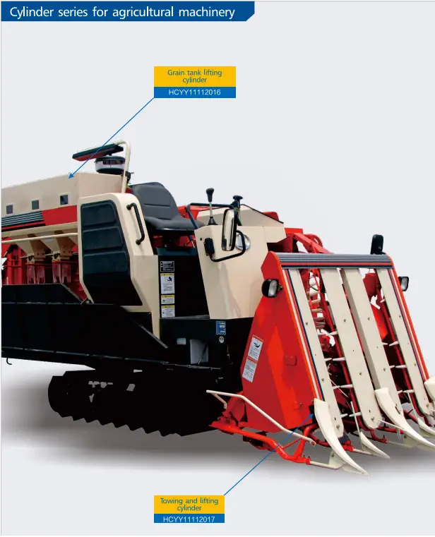
Hydraulic cylinder series for agricultural machinery — including grain tank lift, towing, and auxiliary function cylinders
B2B Procurement — HCYY11112016
Request a Quote, Technical Drawing, or Harvest-Season Bulk Pricing
Our agricultural cylinder team holds full dimensional drawings, seal-kit specifications, and compatibility data for the HCYY11112016 and the complete combine harvester hydraulic cylinder range. Single-unit samples, pre-season stocking orders, and OEM supply programs are all supported with the same technical response standard.
Angebot anfordern
Provide machine model, quantity, and delivery port. FOB/CIF pricing within one business day — including pre-season volume discounts for distributor stocking orders.
Technical Drawing
Full dimensional PDF/DWG drawings, seal-kit part lists, and installation torque specifications for OEM engineers and service teams.
Custom / OEM Supply
Non-standard bore, stroke, or clevis dimension for a specific harvester model? Submit your machine drawing or existing cylinder measurements for a custom quotation.
✓ Lead time 7–15 business days
✓ 100% pressure-tested to 1.5× rated pressure
✓ Seal kits sold separately
✓ T/T or LC at sight
✓ Wooden crate export packing
Material test reports and certificates of conformance available for OEM and fleet accounts. All cylinders pressure-tested before dispatch.