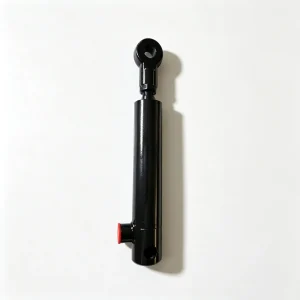
4-Row Corn Hopper Dump Cylinder YM4P.83.04b – 63mm Bore, 695mm Stroke

Full-load grain hopper tipping cylinder producing 49.8 kN at worst-case tipping geometry — no stalling on heavy loads. 29.7 kN retract force controls empty-hopper return through the tipping axis. Dual-lip wiper excludes corn dust on retract; optional end cushion prevents end-of-stroke impact fatigue. OEM and custom stroke/cushion options available. Request pricing or drawings.

Beschreibung

YM4P.83.04b · Corn Harvester Series

4-Row Corn Hopper Dump Cylinder

Mid-stroke, high-force tipping actuator for grain hopper discharge on 4-row self-propelled corn harvesters — engineered for controlled, full-load dump cycles under continuous seasonal use.

Bore 63 mm
Rod 40 mm
Stroke 695 mm
C/C 1200 mm
Part No. YM4P.83.04b
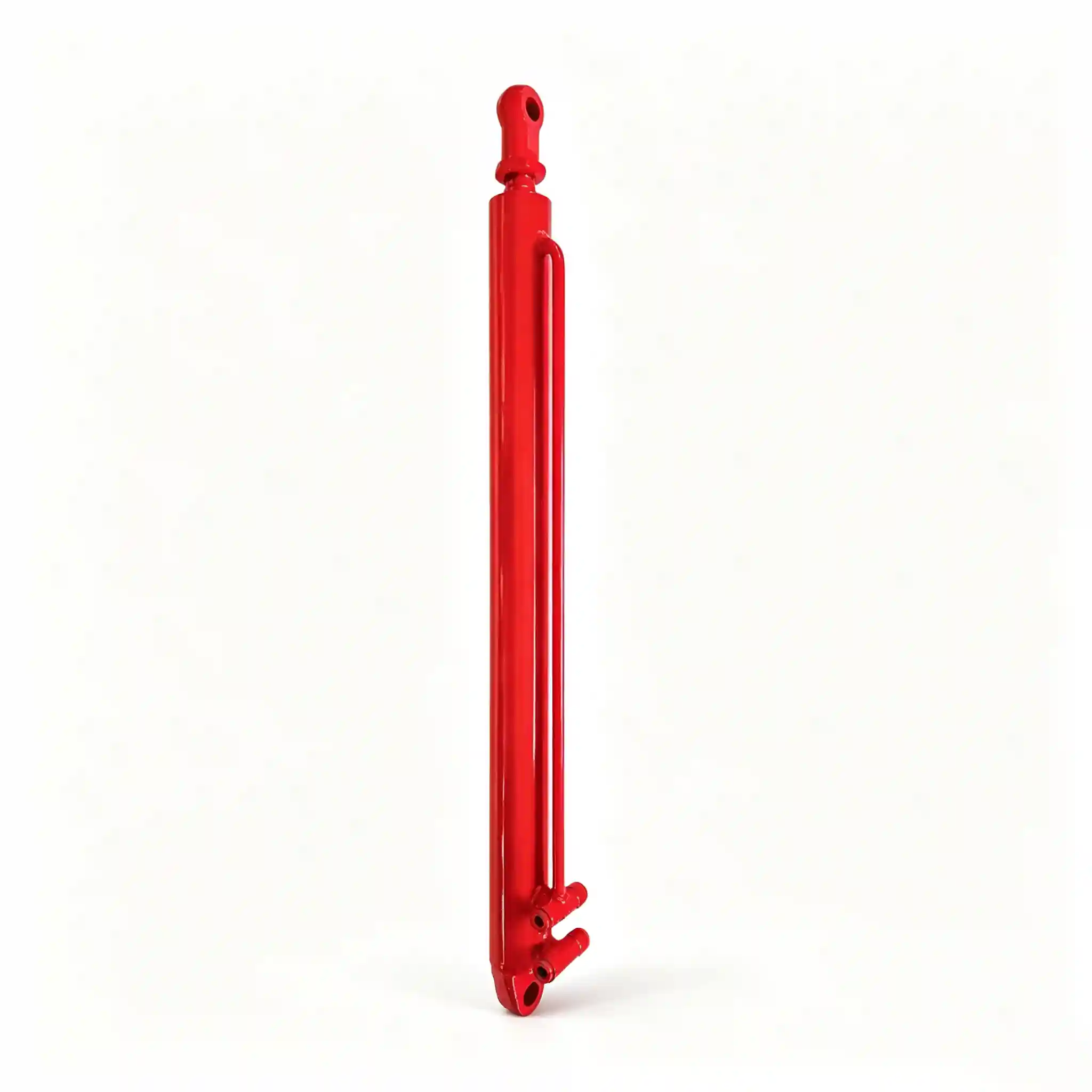
YM4P.83.04b 4-Row Corn Hopper Dump Cylinder — 63mm bore 695mm stroke hydraulic tipping cylinder for grain hopper unloading

Full Specification at a Glance

Bore Diameter

63 mm

Push force ≈ 49.8 kN @ 160 bar — full-load dump capable

Rod Diameter

40 mm

Euler buckling SF 3.1:1 at full 695 mm extension

Stroke

695 mm

Full hopper tilt angle — typically 45–55° pivot arc on 4-row platforms

Mounting Distance

1200 mm

C/C retracted. Extended C/C: 1895 mm.

Rated Pressure

160 bar

Continuous working pressure — standard ag circuit

Surge Pressure

210 bar

End-of-stroke impact rating — proof tested per unit

Rod Chrome

25–30 µm

Hard chrome HV 800+, eddy-current verified full length

Oil Volume (extend)

2.17 L

At 20 L/min circuit flow — full dump completes in ≈ 6.5 s

Seal System

PU Quad-ring
+ PTFE guide

−25 °C to +100 °C, mineral oil & HETG compatible

Mounting Style

Clevis × 2

Ø25 mm pin bore both ends, sintered bronze bush

Push Force (Tip)

49.8 kN

F = 160 bar × π/4 × 63²

Pull Force (Return)

29.7 kN

F = 160 bar × π/4 × (63²−40²)

Buckling SF

3.1 : 1

F_cr ≈ 154 kN vs 49.8 kN push — comfortably above ISO 6020/2 minimum 2.5:1

Full Dump Cycle

≈ 13 s

Extend + retract at 20 L/min circuit flow — matched to operator unloading workflow

The YM4P.83.04b corn hopper dump cylinder controls the most visually dramatic and mechanically loaded movement in the harvest cycle: tipping a grain hopper loaded with up to 800–1,200 kg of shelled corn through a 45–55° arc to discharge into a waiting trailer or pit. It happens dozens to hundreds of times per season, always under full load, always in a timeframe the operator expects to be fast, and always with the full weight of the grain working against — then with — the cylinder as the hopper passes through its tipping axis.

This is not a positioning cylinder. It is a power-stroke actuator where force, speed, and end-of-stroke control determine both cycle efficiency and structural longevity of the entire hopper pivot system. The 63 mm bore, 40 mm rod, 695 mm stroke specification is the product of calculating the force-moment curve across the full tipping arc and selecting a cylinder that keeps system pressure below 140 bar at the worst-case geometry — the first 30° of tip where the moment arm is shortest and the required cylinder force is highest.

4-row corn harvester in field — hopper dump cylinder must tip a fully loaded grain hopper reliably on every unloading cycle

Every hopper dump cycle places the full grain load moment on the cylinder — force and geometry must be correctly matched across the entire tipping arc

4-Row Corn Hopper Dump Cylinder 63mm Bore 695mm Stroke — The Engineering Behind Every Tipping Cycle

Q

Why does the required cylinder force change as the hopper tips — and how does the 63mm bore address this?

A hopper dump mechanism is a rotating lever, not a linear slide. The cylinder force required to tip the hopper is determined by the moment equation: F_cyl × L_cyl_arm = M_load × L_load_arm. Both moment arms change continuously as the hopper rotates through its arc, and they do not change in proportion to each other. On a 4-row platform, the geometry typically produces a worst case at approximately 20–30° of tilt — early in the dump — where the load moment arm is long but the cylinder moment arm is still short. This is the peak force point, and it is what sizes the bore.

For a 1,000 kg hopper load with a 0.6 m load moment arm at worst-case geometry, the required tip force approaches 44 kN. The 63 mm bore at 160 bar delivers 49.8 kN — providing an 13% force margin above the worst-case geometry point without requiring circuit pressure above the standard 160 bar working limit. A 56 mm bore would produce only 39.4 kN, requiring either a pressure increase to 175–180 bar or accepting that the system will stall on a heavily loaded hopper at the worst-case geometry. Neither outcome is acceptable in production.

Q

The hopper passes through its tipping axis during discharge — what happens to the cylinder load at that point?

This is the most mechanically interesting moment in the dump cycle, and the one most often overlooked in cylinder selection. Once the hopper centre of gravity crosses the pivot axis — typically at 50–60° of tilt — the load reverses: the hopper now wants to continue tipping under gravity, and the cylinder transitions from a pushing actuator to a restraining actuator. The retract side of the circuit (rod side, 29.7 kN capacity) must now control the rate of descent as the grain slides out and the empty hopper returns. If the retract force is insufficient, or if the circuit relief valve on the rod side is incorrectly set, the hopper will snap to full extension uncontrolled — a structural shock event that damages both the cylinder mount and the hopper pivot bearings.

The 63/40 geometry gives 29.7 kN retract capacity — adequate to control the return of an empty hopper (typically 150–250 kg) at any descent rate achievable within the circuit flow rate. Machines that have had the original cylinder replaced with a thinner-rod substitute commonly show accelerated wear at the hopper pivot pin and bracket — the consequence of under-controlled return cycles.

Q

Why is end-of-stroke cushioning relevant on a hopper dump cylinder, when most agricultural cylinders run without it?

On a short-stroke engagement or chopper cylinder, the kinetic energy at end-of-stroke is low — the piston mass is small and the stroke is short. On a 695 mm stroke cylinder moving a 63 mm piston at a flow-rate-limited velocity of approximately 107 mm/s (at 20 L/min), the kinetic energy of the moving assembly at end-of-stroke approaches a level where a hard stop generates a pressure spike in the 80–120 bar range above circuit pressure. Repeated over hundreds of dump cycles per season, this compressive fatigue at the piston-end-cap contact face is a known failure initiator in dump-duty cylinders.

The YM4P.83.04b is available with an adjustable bore-side end-of-stroke cushion as a factory option — a tapered spear on the piston that progressively throttles return oil over the last 30–40 mm of stroke, decelerating the piston before contact. For OEM integrators specifying this cylinder on new platform builds, the cushion option is recommended wherever the full-extend position is a hard mechanical stop rather than a load-controlled resting position.

Q

How does the dump cylinder’s contamination environment differ from other cylinders on the same machine?

The hopper dump cylinder operates in a uniquely challenging contamination zone. During the dump cycle, shelled corn, husks, and fine starch dust are actively airborne around the cylinder position. More critically, the return stroke retracts a rod that may have grain dust adhered to it from the dump phase — a fine, mildly hygroscopic particulate that packs into the wiper seal gap and, over repeated cycles, acts as a mild abrasive against the chrome rod surface.

The dual-lip wiper fitted to this cylinder — an outer polyurethane scraper lip plus a secondary exclusion lip — is specifically designed to handle particulate contamination during retract. The outer lip removes bulk material; the secondary lip maintains a film of hydraulic oil on the rod surface during the final 10 mm of retract, providing lubrication for the inner rod seal rather than allowing the rod to enter the seal contact dry. This is not standard on all cylinder designs and is a meaningful durability differentiator in this application.

Combine Harvester Hopper Actuator OEM Construction — Materials and Process Standards

Cylinder Tube

E355 cold-drawn seamless, 63 mm bore × 9 mm wall. Honed Ra ≤ 0.4 µm. External finish: zinc phosphate + PU topcoat, 80 µm DFT minimum, 500-hour salt spray tested.

Chromstange

Ck45 steel, ground Ra ≤ 0.2 µm. Hard chrome 25–30 µm, HV 800+. Post-chrome ground h6. At 695 mm stroke, rod straightness verified ≤ 0.2 mm total — rejects above this threshold before chrome.

Wiper / Seal Pack

Dual-lip PU wiper (outer scraper + secondary film-retention lip). Inner: dual-lip PU rod seal. Piston: quad-ring PU primary + PTFE backup. Full seal kit catalogued as separate spare.

End Fixings

Clevis both ends, Ø25 mm pin bore, sintered bronze self-lubricating bush, grease nipple. Clevis wall 15 mm machined steel. Cushion option: adjustable tapered spear, bore-side, factory-fit.

QC Protocol

Hydrostatic proof 210 bar × 60 s per unit. Full-stroke × 5 cycles under rated load. External leakage check both ports. Dimensional audit: C/C, stroke, pin bore. Batch records available to OEM.

Corn crop at harvest — grain hopper dump cylinder must tip a full-load hopper reliably across hundreds of unloading cycles per season

A full hopper dump at peak harvest — the cylinder manages the entire load moment from first tilt to empty return, every cycle

Hydraulic Cylinder for Corn Harvester Grain Hopper Tipping — Service Life Under Realistic Seasonal Load

Procurement teams sourcing this cylinder for a service network should understand the actual cycle loading it faces over a season. On a 4-row self-propelled corn harvester operating at typical field capacity, the hopper fills in 15–25 minutes of harvesting. Over a 10–12 hour harvest day, the operator performs 25–40 full dump cycles. Across a 30-day harvest season, this totals 750–1,200 full extend-retract cycles, every one under full grain load on extension and controlled empty-hopper return on retraction.

Cycles per Season

750–1,200

Full load extend + controlled retract. Seal design validated to 5,000 cycles minimum in laboratory endurance testing.

Recommended Inspection

End of season

Check rod chrome, inspect wiper for corn-dust compaction, grease pin bushes. Replace seal kit if any weeping present.

Seal Kit Lead Time

< 5 days

Seal kit stocked and catalogued separately. Field replacement time ≈ 60 min with standard C-spanner tooling.

Pin Bush Service

2–3 seasons

Sintered bronze self-lubricating. Replace when radial play exceeds 0.8 mm — excessive pin play accelerates rod scoring.

Combine Harvester Hopper Unloading Cylinder — OEM Custom Configurations and Batch Supply

Standard YM4P.83.04b ships from stock. Integrators developing proprietary hopper systems can modify the following parameters without tooling surcharge at qualifying volumes:

  • Stroke: 550–850 mm within current tube and rod family. Extended strokes require updated Euler buckling review — provided as standard with quotation.
  • Mounting distance (C/C): Specify retracted C/C to 1 mm resolution. Both retracted and extended C/C provided on dimensional drawing for bracket design review.
  • End-of-stroke cushion: Bore-side adjustable cushion — standard option, no surcharge. Recommend for hard-stop full-extend applications.
  • Rod end style: Clevis, spherical rod eye, knuckle joint, or welded flange — to customer drawing.
  • Port standard: BSP G1/2″, SAE ORB #8/#12, NPT 1/2″, BSPT. Side or end entry.
  • Seal material: Standard PU/PTFE; FKM for HETG biodegradable fluid; NBR for sealed-environment storage applications.
  • Surface coating: Standard zinc phosphate + PU coat; black oxide; customer RAL colour code.
  • OEM marking: Part number engraving, private label, colour coding at MOQ ≥ 30 pcs per configuration.

All custom configurations supplied with 2D dimensional drawing, Euler buckling safety factor report, and STEP file on request — before production confirmation. Standard lead time 7–15 business days ex-works; custom 20–35 business days depending on volume and specification.

Ready to Source or Specify?

Request Drawings, Buckling Report, OEM Pricing, or Custom Dump Cylinder Engineering

Hopper dump cylinders carry full grain load on every cycle. Our technical team provides force-moment curve analysis, Euler buckling calculations, 2D/3D drawings, and material certifications — standard for all OEM and distribution enquiries on this product.