विवरण
What the WPWDKT Worm Wheel Reducer Does — and Where It Fits
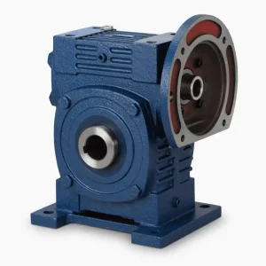
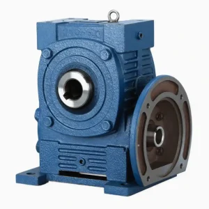
The WPWDKT Worm Wheel Reducer is a worm wheel reducer designed around a T-type output flange configuration. Where most WP worm gear reducer variants deliver torque through a standard keyed shaft, the KT suffix means the output face presents a bolt-on flange — a meaningful distinction when you’re mounting a driven component directly to the gearbox face rather than through a coupling arrangement.
At its core, the WPWDKT converts rotary motor speed into a lower-speed, higher-torque output across eight selectable ratios (1:10 to 1:60). The worm and worm wheel mesh geometry achieves this in a single stage with a center distance of 40 to 250 mm, keeping the overall envelope compact relative to equivalent multi-stage helical arrangements. The unit accepts standard AC motor mounting via IEC B5 and B14 flanges, making it a direct bolt-on for the majority of induction and VFD-controlled motors in service today — commonly described as a worm gearbox with motor pairing.
Internal components follow established material specifications: the worm wheel is cast from tin-bronze alloy (Copper-10-3#) for low friction and good wear resistance against the hardened steel worm. The worm itself is 20CrMnTi steel, carburized and quenched to a surface hardness of 56–62 HRC, then ground to Ra 0.8 μm — the same finishing standard applied to precision ground lead screws. The 45# chromium steel output shaft is supported on C&U bearings with KSK oil seals throughout.
Technical Specifications of Worm Wheel Reducer
| Parameter | Value / Detail |
|---|---|
| Model Range | WPWDKT 40 / 50 / 60 / 70 / 80 / 100 / 120 / 135 / 155 / 175 / 200 / 250 |
| Gear Ratio Options | 1:10 · 1:15 · 1:20 · 1:25 · 1:30 · 1:40 · 1:50 · 1:60 |
| Housing Material | HT200 Die-Cast Grey Iron |
| Worm Wheel Material | Tin-Bronze Alloy Copper-10-3# |
| Worm Material & Finish | 20CrMnTi — carburized & quenched, 56–62 HRC, ground to Ra 0.8 μm |
| Output Shaft | 45# Chromium Steel — T-type flange output configuration |
| Bearing | C&U Bearing |
| Seal Standard | KSK Oil Seal |
| Input Power Range | 0.12 kW – 15 kW |
| IEC Flanges | 56B14 · 63B14 · 63B5 · 71B14 · 80B14 + custom frames |
| Lubricant Type | ISO VG 220/320 Mineral or PAO Synthetic |
| Standard Color | Blue / Green — custom RAL on request |
| Packing | Export carton + wooden case |
| Warranty | 12 months from shipment |
| Industries Served | Food · Ceramics · Chemical · Packaging · Dyeing · Woodworking · Glass |

▼ Dimensional Data by Frame Size (mm / kW / kg)
| Size | Power (kW) | Ratio | AC | B | CC | LL | M | N | E | G | LA | LB | LC | S | W×Y | Wt(kg) |
|---|---|---|---|---|---|---|---|---|---|---|---|---|---|---|---|---|
| 40 | 0.12 | 1/5–1/60 | 75 | 85 | 40 | 63 | 90 | 187 | 70 | 12 | 115 | 95 | 140 | 16 | 6×18.8 | 5.4 |
| 50 | 0.18 | 1/5–1/60 | 83 | 105 | 50 | 70 | 120 | 226 | 95 | 14 | 115 | 95 | 140 | 20 | 6×22.8 | 8.5 |
| 60 | 0.37 | 1/5–1/60 | 91 | 110 | 60 | 80 | 130 | 257 | 105 | 15 | 130 | 110 | 160 | 25 | 8×28.3 | 12 |
| 70 | 0.37–0.75 | 1/5–1/10 | 109–111 | 130 | 70 | 95 | 150 | 305 | 115 | 20 | 130–165 | 110–130 | 160–200 | 30 | 8×33.3 | 17 |
| 80 | 0.75–1.5 | 1/5–1/15 | 125 | 150 | 80 | 105 | 170 | 350 | 135 | 20 | 165 | 130 | 200 | 35 | 10×38.3 | 26 |
| 100 | 1.5 | 1/20–1/60 | 148 | 160 | 100 | 135 | 190 | 410 | 155 | 22 | 165 | 130 | 200 | 40 | 12×43.3 | 40.5 |
| 120 | 2.2–3.0 | 1/25–1/30 | 181 | 175 | 120 | 160 | 230 | 494 | 180 | 25 | 215 | 180 | 250 | 45 | 14×48.8 | 59 |
| 135 | 3.0–4.0 | 1/40–1/60 | 202 | 210 | 135 | 185 | 250 | 559 | 200 | 30 | 215 | 180 | 250 | 60 | 18×64.4 | 89 |
| 155 | 5.5 | 1/40–1/60 | 247 | 256 | 155 | 220 | 275 | 605 | 220 | 35 | 265 | 230 | 300 | 70 | 20×74.9 | 138 |
| 175 | 5.5–7.5 | 1/40–1/60 | 262 | 282 | 175 | 240 | 310 | 675 | 250 | 40 | 265 | 230 | 300 | 80 | 22×85.4 | 172 |
| 200 | 11.0 | 1/40–1/60 | 285 | 320 | 200 | 280 | 360 | 749 | 290 | 40 | 300 | 250 | 350 | 85 | 22×90.4 | 246 |
| 250 | 11.0–15.0 | 1/40–1/60 | 330 | 400 | 250 | 315 | 460 | 920 | 380 | 45 | 300 | 250 | 350 | 110 | 28×116.4 | 400 |
All dimensions in mm. For double-stage or custom configurations, contact factory.
Problems the WPWDKT Worm Wheel Reducer Eliminates
Coupling Misalignment Failures
The T-type flange output eliminates the floating shaft-to-coupling joint that causes vibration and seal wear on conventional shaft-output gearboxes. Driven components bolt directly to the output face — one alignment check, done.
Ratio Gaps in Your Drive Line
With 8 ratios from 1:10 to 1:60 and double-stage cascading available, there is effectively no output speed requirement the WPWDKT series cannot cover — without switching to a different gearbox family or adding a belt-and-pulley stage.
Uncontrolled Backdrive Risk
At ratios above 1:30, the WPWDKT exhibits natural self-locking behaviour — the output cannot back-drive the worm. This provides inherent load-holding on inclined conveyors, hoists, and gate actuators with no brake required in many applications.
Incompatible Motor Frames
The multi-flange input (56B14 through 80B14 and custom) means the same gearbox body accepts IEC motors from 0.12 kW upward. Motor swaps during a production change-over take under 20 minutes without machining or adapter fabrication.
WPWDKT vs. a Standard Worm Wheel Reducer
The differences are specific and worth spelling out before you specify:
| Attribute | WPWDKT Series | Standard Shaft-Output WP Reducer |
|---|---|---|
| Output Interface | T-type bolt-on output flange | Keyed output shaft requiring a coupling |
| Load Attachment | Direct face-mounting — zero coupling slack | Coupling introduces angular compliance & backlash |
| Alignment Requirement | One-time bolt-pattern alignment | Requires precision shaft-to-shaft alignment on every install |
| विशिष्ट अनुप्रयोग | Rotary tables, turntables, indexing fixtures, drum drives | Conveyors, extruders, general-purpose shaft drive |
| Housing | HT200 die-cast iron — same as WP standard | HT200 die-cast iron |
| Self-Locking (ratio ≥1:30) | Yes — inherent to worm geometry | Yes — inherent to worm geometry |
Structural Features of the Worm Gear Reducer
Line Contact for Higher Load Capacity
The worm and worm wheel mesh in line contact — not point contact as in crossed-axis helical gears. This spreads load across multiple teeth simultaneously, making the cast iron worm gear speed reducer capable of carrying substantially higher torque per unit size than a comparable helical pair at the same center distance.
High Ratio in a Single Stage
A single-stage worm set delivers ratios from 1:10 to 1:60 — a range that would require two or three stages in a helical gearbox. The result is a more compact housing for the same output ratio, reducing the footprint of the universal worm gearbox in constrained machine installations.
Self-Locking at High Ratios
When the worm lead angle falls below the equivalent friction angle of the mesh, the reducer becomes self-locking. At 1:40 and above, the WPWDKT will hold a suspended or inclined load without power — functioning as a built-in safety brake on lifting and positioning equipment.
Multi-Tooth Simultaneous Engagement
Because the worm is essentially a threaded screw meshing into the wheel, multiple teeth are in contact at any given instant. This distributes transmission force across several contact zones at once — the mechanism behind the smooth, low-noise output that distinguishes a well-specified heavy duty worm drive gearbox from gear-noise-prone alternatives.
Efficiency & Thermal Considerations
Single-stage worm efficiency ranges from 70–92% depending on ratio and lubrication — lower than helical gears. The relative sliding motion between worm and wheel generates heat; this is managed in the WPWDKT by an HT200 iron housing with ~35% better thermal conductivity than aluminium die-cast alternatives, plus compatibility with PAO synthetic oil to extend oil-change intervals to 8,000 hours.
Main Components
Core parts: tin-bronze worm wheel (Copper-10-3#), 20CrMnTi worm, C&U deep-groove bearings, HT200 iron housing, KSK oil seals. Secondary hardware: end caps, vent plug, fill/drain bolts, IEC flange adapter studs. All wear-parts are stocked separately for fast field replacement.
अक्सर पूछे जाने वाले प्रश्नों
Q1: Is the WPWDKT series quieter than a standard worm wheel reducer?
On equivalent sizes and ratios, the WPWDKT measures within ±2 dB(A) of a standard shaft-output WP unit at rated load — the T-type flange output doesn’t affect gear mesh acoustics. At size 80, expect <65 dB(A) at 1 m no-load. The bronze-on-hardened-steel mesh is inherently quieter than all-steel gear pairs at any ratio above 1:10.
Q2: What mounting orientations does the WPWDKT support?
Foot-mount, flange-mount, and output-face-mount are all supported. The oil fill position must be re-set for each orientation per the supplied diagram. Incorrect fill orientation is the primary cause of premature seal failure — always verify before first start.
Q3: What oil grade is recommended for a worm gear reducer manufacturers typically specify?
ISO VG 220 mineral for ambient 10–40°C; VG 320 above 40°C. PAO synthetic extends drain intervals to 8,000 hours. Never mix oil types. First drain at 200–300 hours to remove break-in debris, regardless of oil type.
Q4: Can the WPWDKT Worm Wheel Reducer run on a VFD-controlled motor?
Yes. The HT200 housing and bronze wheel tolerate VFD harmonic content without modification. Maintain minimum motor frequency at 30% of rated speed (≥15 Hz on 50 Hz supply) to ensure adequate splash lubrication at the worm contact zone. Below this threshold, add a pressurised lube system on size 155 and above.
Q5: Are spare worm wheels and worms stocked as separate parts?
Yes. Tin-bronze wheels and ground worms for sizes 40–175 are held in inventory. Sizes 200 and 250 spare gear sets have a 7–10 working day lead time. Always specify the size code plus ratio when ordering — worm tooth count changes with ratio at the same center distance.
Packaging & Transportation
Export-Grade Packaging
Units ≤60 kg in double-wall cartons; larger sizes in fumigated wooden crates with foam blocking. Pallet configurations per customer drawings on request.
QC-Tested Before Packing
No-load run cycle, noise check, and seal inspection on every unit. QC report issued for orders of 5+ units. Delivery on time with correct specs confirmed before dispatch.
Matched Transport Mode
Air express for urgent small parcels; LCL or FCL ocean freight for pallet loads. We choose the mode by weight and delivery deadline — or follow your preferred forwarder instructions.
Arrival & After-Sales Support
Inspect units on receipt before signing. Photograph any transit damage immediately. Claims processed within 48 hours of photo evidence. 12-month warranty parts dispatched within 5 business days of a verified claim.

Customer Reviews
“We installed 8 WPWDKT-135 units on a rotary indexing table for a ceramics kiln line. After 16 months of two-shift operation, the flange-output configuration has given us zero coupling failures — which was the problem we were trying to solve. Dimensional consistency across all 8 units was within 0.2 mm on every bolt circle.”
“I asked myself: do I really need a T-flange worm reducer, or am I just overcomplicating things? Turns out, yes, I needed it — and yes, it works perfectly. Bolted straight to the drum on my woodworking line with no coupling drama. The self-locking at 1:40 means I can go get a coffee and the wood stays exactly where I left it. 10 out of 10, would bolt again.”
Complete Drive Solutions
The WPWDKT is one part of a complete drive train. All components below are available from us — order the full assembly in one transaction, shipped together.
Standard AC / IEC Motors
B3/B5/B14 IEC frame motors from 0.12–15 kW. Pre-matched to WPWDKT input flanges.
ब्रेक मोटर्स
DC-release brake motors for positioning and safety-hold applications requiring faster stop than self-locking provides.
Flexible / Jaw Couplings
Polyurethane spider jaw couplings for shaft-output secondary connections. Sizes 14–80 mm bore.
Sprockets & Roller Chains
Hardened steel sprockets from #25 to #80 pitch. Simplex and duplex roller chains. Stocked in standard lengths.
Splined Shafts & Yokes
PTO and industrial splined shafts machined to ±0.02 mm pitch tolerance.
Torque Limiters
Mechanical slip-clutch overload protectors for shock-load environments. Trip torque adjustable.
✔ All of the above components are sold directly from our catalog. Contact us with your drive system spec and we will quote the complete package — gearbox, motor, couplings, and chain in one order.
Explore Our Full Power Transmission Range
If the WPWDKT Worm Wheel Reducer isn’t the right fit for your application, one of these series will be. We manufacture them all:
ग्रहीय गियरबॉक्स
हेलिकल गियरबॉक्स
Bevel-Helical Reducer
Cycloidal Drive
WPWDKA / WPWDKS Series
Ready to order or need a custom build?
Tell us your required size, ratio, motor frame, and quantity. In-stock sizes 40–135 ship in 3 business days. Selection assistance is always free.