描述
YM4P.83.02b · Corn Harvester Series
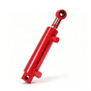
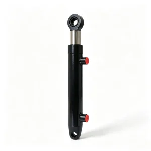
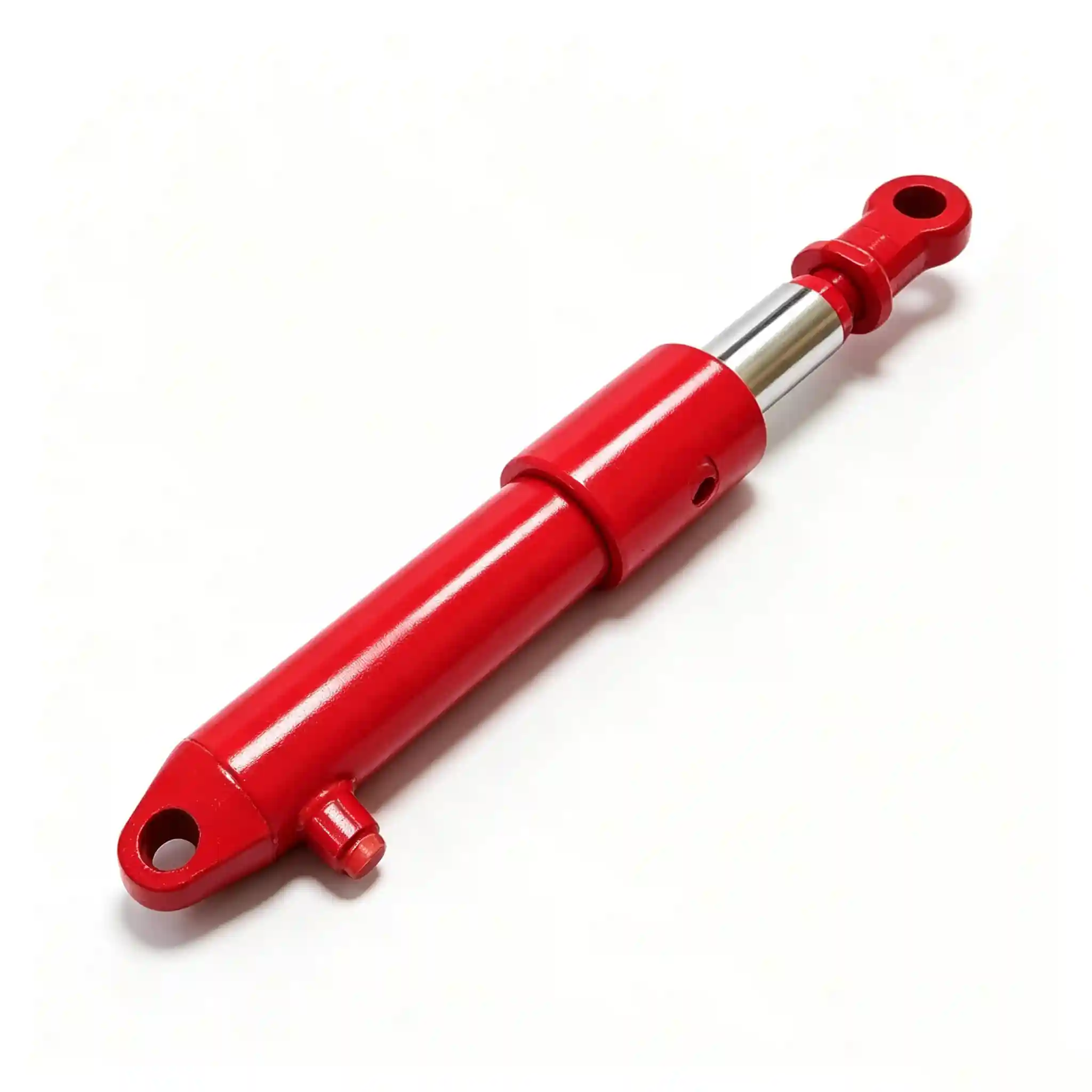
Corn Header Lift Cylinder — High-Force, Low-Drift Header Height Control for 4-Row Corn Harvesters
Part No. YM4P.83.02b | Bore: 56 mm | Rod: 50 mm | Stroke: 300 mm | C/C: 660 mm
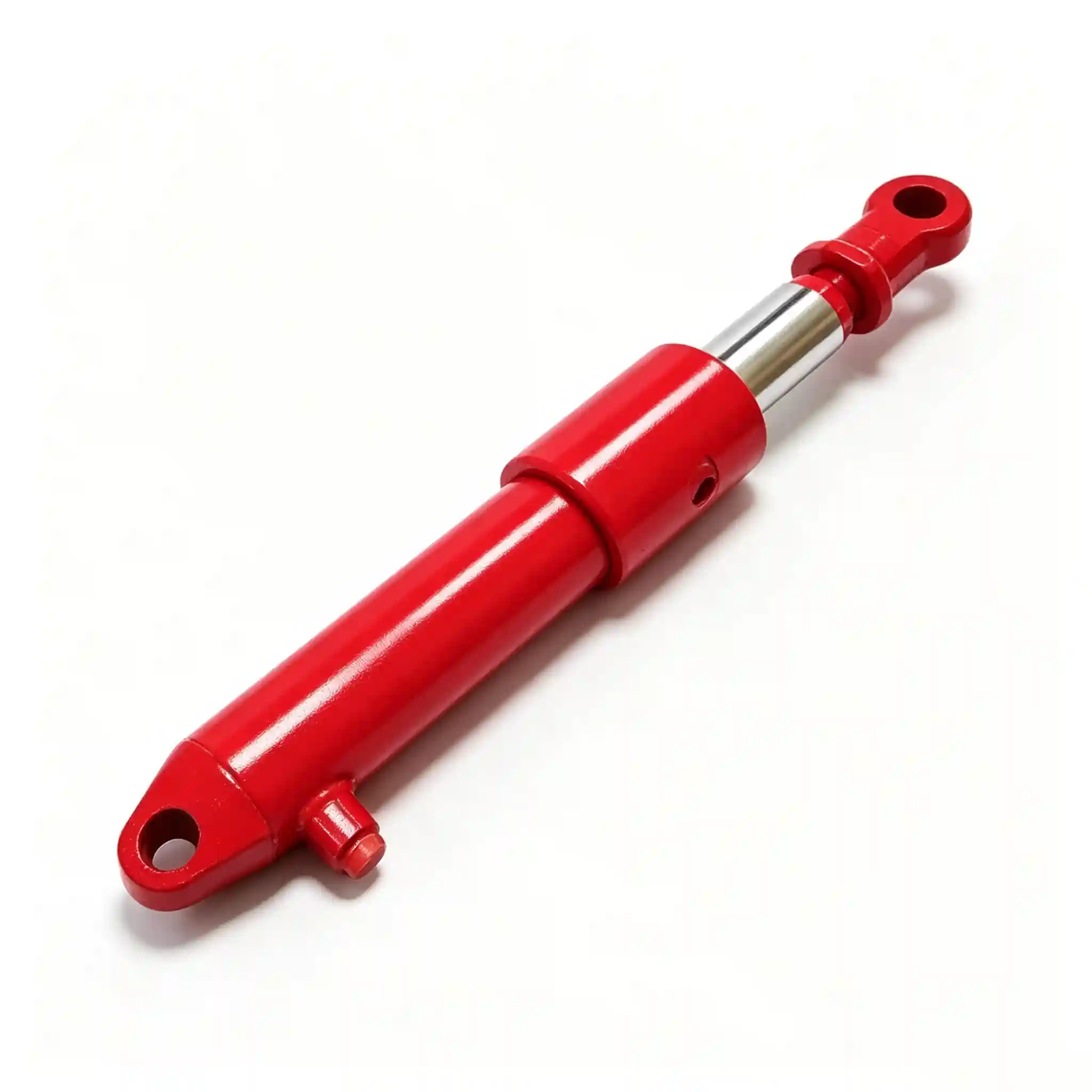
YM4P.83.02b Header Lift Cylinder
The YM4P.83.02b corn header lift cylinder controls one of the most consequential adjustments a corn harvester operator makes during a working day: the height of the cutting header above the ground. Get this wrong — too low and you’re ingesting soil and rocks through the snapping rolls; too high and you’re leaving ears on the stalks. The hydraulic cylinder that controls this position must hold the header absolutely steady under the combined weight of a multi-row cutting platform and the dynamic loads of forward travel across uneven ground.
With a 56 mm bore and a notably thick 50 mm rod — giving a rod-to-bore ratio of 0.893 — this cylinder is configured as near-equal-area for a reason: the retract force must match the extend force closely enough to hold header height against both gravity and upward ground reaction forces with minimal position drift.
Hydraulic Cylinder for Corn Harvester Header Height Adjustment — Complete Technical Parameters
| 范围 | Value | Engineering Note |
|---|---|---|
| Bore Diameter (D) | 56 mm | At 160 bar working pressure, push force ≈ 39.4 kN — sufficient to raise a loaded 4-row header assembly (typically 450–600 kg) with full safety margin and speed. |
| Rod Diameter (d) | 50 mm | Unusually thick rod relative to bore (rod/bore ratio = 0.893). This is a deliberate heavy-duty specification — the thick rod resists buckling under off-axis loads from header sway and provides near-equal retract force for header lowering control. |
| Stroke (L) | 300 mm | Full stroke of 300 mm covers the complete header height range — from minimum stubble clearance (~150 mm) to maximum transport/headland height. Provides fine incremental control across the full working range. |
| Mounting Distance (C/C) | 660 mm | Center-to-center retracted. The 660 mm C/C is the governing dimension for frame bracket compatibility. Always verify against platform bracket before ordering a replacement. |
| Rated Working Pressure | 160 bar (2,320 psi) | Standard agricultural hydraulic circuit pressure. Cylinder tube rated to 2.5× working pressure per ISO 6020/2 test protocol. |
| Peak / Surge Pressure | 250 bar (3,625 psi) | Covers transient spikes from emergency stop or obstacle impact on the header. Piston seal rated for full surge pressure without extrusion. |
| Rod Surface Treatment | Hard chrome, 25–30 µm | On a 50 mm rod, even minor chrome pitting rapidly accelerates rod seal wear due to the large circumferential contact area. Specification requires 25 µm minimum chrome depth across full rod length. |
| Internal Leakage | ≤ 3 cc/min at rated pressure | Low bypass is critical here. A cylinder with excessive piston seal leakage will allow the header to slowly drop during stationary work (headland turns, inspections), requiring constant operator correction. |
| Seal System | PU quad-ring + PTFE guide | Quad-ring geometry on piston maintains sealing force across temperature cycles without the permanent set that degrades standard O-ring piston seals in seasonal-use equipment. |
| Cylinder Tube Material | E355 cold-drawn seamless | Honed bore Ra ≤ 0.4 µm. Wall thickness calculated for 250 bar burst with a safety factor of 4:1 on tube yield strength. |
Engineering Reference · Force & Rod Calculations
Push Force (header raise): F = 160 bar × π/4 × (0.056)² ≈ 39,437 N (39.4 kN)
Pull Force (header lower): F = 160 bar × π/4 × (0.056² − 0.050²) ≈ 8,670 N (8.7 kN)
The annular area is small (only 477 mm² vs. 2,463 mm² full bore) because the 50 mm rod occupies 80% of the bore cross-section. Pull force of 8.7 kN is more than adequate for header lowering — gravity assists the retract — while the 39.4 kN push force provides a 6:1 safety margin over a 600 kg header weight (5.9 kN at pivot).
Rod buckling check (Euler): A 50 mm solid chrome rod at 300 mm stroke — with a slenderness ratio of ~6 — is far below the critical buckling load. This is an important validation for procurement engineers: the thick rod is not oversized for aesthetics but is the correct engineering specification for an extended, laterally loaded header-lift linkage.

Header height precision directly affects grain loss rate and harvesting efficiency
Why the 56mm Bore / 50mm Rod Specification Is Not Interchangeable with Standard Lift Cylinders
The near-equal bore-to-rod diameter (56/50) of this cylinder is unusual in agricultural hydraulics, where most lift cylinders use a rod diameter of 55–70% of bore. This specification is a precise engineering response to the operating conditions of a front-mounted corn header:
- Off-axis bending loads: As the harvester traverses a furrow or ridge, the header can rock laterally by 5–8° relative to the main frame. The cylinder pivot absorbs a portion of this as bending moment on the extended rod. A standard 32 mm or 36 mm rod on a 56 mm bore cylinder would develop significant deflection at mid-stroke, accelerating rod-seal wear and risking rod fatigue cracking after 2–3 seasons of intensive use.
- Vibration fatigue: The snapping rolls and gathering chains on a corn header generate structured vibration at 40–120 Hz during operation. These vibrations transmit through the header frame directly into the lift cylinder mounting pins and rod. The 50 mm solid rod has a bending stiffness approximately 2.6× that of a 38 mm rod at the same length — fundamentally different fatigue behaviour.
- Position hold under oscillating load: If the header is held at a fixed height while harvesting, the cylinder is effectively a structural member resisting both the header weight and the dynamic vertical loads from crop resistance. Piston seal leakage under cyclic loading is higher in cylinders with thin rods (lower compression stiffness) — the thick rod reduces this effect.
- Consequence of substitution: Replacing this cylinder with a standard-rod equivalent (same bore, 32–36 mm rod) is a false economy. The maintenance interval shortens materially, and the failure mode — a rod bent enough to score the wiper seal — typically requires cylinder replacement rather than a field seal kit swap.
OEM Combine Header Cylinder Construction — Material and Process Standards
Cylinder Tube
E355 cold-drawn seamless steel tube, honed to Ra ≤ 0.4 µm. Wall thickness: 8 mm — calculated for 4:1 safety factor on tube yield at 250 bar burst. External surface: zinc phosphate primer + polyurethane topcoat, 80 µm minimum DFT, salt-spray tested to 500 hours.
Chrome Rod
Ck45 (1.1191) steel core, ground and polished to Ra ≤ 0.2 µm before chrome plating. Hard chrome 25–30 µm, HV 800+. Post-plate ground to h6 tolerance for seal fit. At 50 mm diameter, the rod’s second moment of area is 307,000 mm⁴ — providing the structural rigidity this application demands.
Piston & Seals
Cast iron piston with bronze guide rings. Primary piston seal: PU quad-ring with PTFE energised backup. Rod seal: dual-lip PU. Wiper: polyurethane with steel-reinforced exclusion lip. All seals rated −25 °C to +100 °C on ISO VG 46/68 mineral oil.
End Fixings
Both ends: clevis-type pin mount, Ø25 mm pin bore, with grease nipple for lubrication of the pin/bush interface. Bush material: sintered bronze (self-lubricating). Clevis eyes machined to H7 tolerance for pin fit. Grease type: NLGI #2 lithium-complex, compatible with food-grade alternatives for USDA-regulated harvest environments.
Header Height Precision — How Cylinder Drift Rate Translates to Grain Loss in the Field
For OEM engineers and technically sophisticated distributors, it is worth quantifying exactly what cylinder performance means in agronomic terms. Research data from major corn-growing regions consistently shows that header height is the single largest controllable variable in ear-loss rate:
- Optimum cutting height on erect corn is typically 150–250 mm above soil level, keeping the snapping rolls above the first stalk node to avoid ingesting soil while capturing all ears.
- A 50 mm drop in header height from drift during a 200 m field run can pull bottom-of-stalk material through the rolls, increasing wear on snapping plates and adding soil contamination to the grain tank.
- Internal leakage specification of ≤ 3 cc/min on this cylinder translates to a position drift rate of less than 1.2 mm per minute at full header weight — in practical terms, essentially zero drift across a standard field pass.
A cylinder with degraded piston seals (leakage >15 cc/min, typical of a worn-out or generic replacement) can drift 6 mm per minute under load. On a headland stop of 3 minutes while the operator turns and re-aligns, that’s an 18 mm position error requiring manual correction on every pass — not a minor inconvenience, but a repeating interruption to the operator’s attention and machine throughput.

Consistent header height across 200–400 m field runs demands near-zero cylinder drift
Platform Compatibility and Fit Verification Guide
The YM4P.83.02b is designed for the YM4P platform. For distributors sourcing replacements across a mixed fleet, the following verification points ensure correct fitment:
| Check Point | Specification | Why It Matters |
|---|---|---|
| C/C retracted | 660 mm ± 2 mm | Controls header height at fully lowered position. Mismatch causes incorrect minimum cutting height. |
| Stroke | 300 mm | Sets maximum header transport height. Short-stroke substitutes will limit headland clearance. |
| Pin bore diameter | Ø25 mm (both ends) | Standard 4-row YM4P platform. Confirm against bracket pin before ordering if machine has been modified. |
| Port thread | BSP G1/2″ (or SAE #8 ORB) | Match to hose fitting specification. Specify at order if machine uses SAE ports. |
| Rod diameter | 50 mm (do not substitute 38 mm or 45 mm rod equivalent) | As detailed above — rod diameter is a structural specification, not interchangeable with a “same bore” generic cylinder. |
Combine Harvester Header Lift Cylinder Specs — OEM & Custom Supply Options
Standard YM4P.83.02b is produced in batches and available from stock. Integrators and OEM procurement teams requiring platform-specific modifications can specify the following without tooling surcharge at qualifying volumes:
Stroke Adjustment
250–380 mm within current tube-length envelope. Extended strokes up to 450 mm with tube extension, per engineering review.
Mounting Distance
C/C adjustable ±50 mm from standard 660 mm. Specify to 1 mm resolution on order.
Port Standard
BSP G1/2″, SAE ORB #8/#12, NPT 1/2″, BSPT — all available. Specify at order to avoid field adapters.
Rod End Style
Clevis, spherical rod eye, threaded male rod end, or integrated positional sensor mount (for electronic header height systems).
Seal Material
Standard PU/PTFE, NBR for high-temperature circuits, FKM (Viton) for biodegradable HETG and fire-resistant HF-D fluids.
OEM Branding
Private-label part marking, custom colour coding, and OEM part number engraving available at MOQ ≥ 50 pcs per configuration.
2D dimensional drawings and 3D STEP files are provided for all standard and custom configurations prior to production confirmation. Lead time: standard stock configurations 7–15 business days ex-works; custom specifications 20–35 business days depending on complexity and volume.
Ready to Specify or Procure?
Request Technical Drawings, Batch Pricing, or Custom Engineering Review
OEM procurement teams and engineering departments receive full 2D/3D documentation, material certifications (mill certs on request), and a technical response — not a catalogue PDF. We support design reviews before first order.