Description
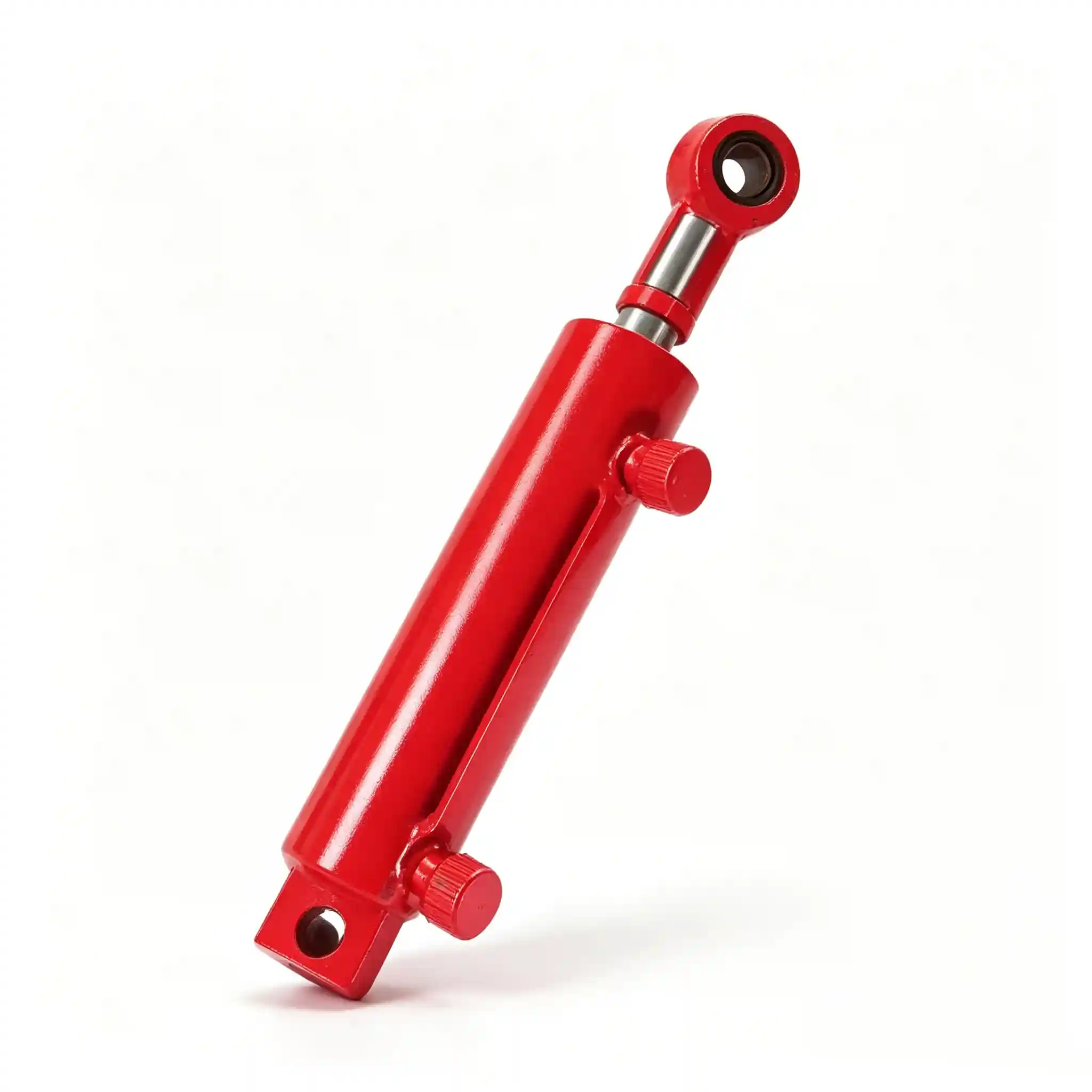
Model · YD40-245-D5
Combine Unloading Auger Cylinder — YD40-245-D5
Every bushel of grain a combine harvests has to pass through one final mechanical stage before it reaches the trailer: the unloading auger. The combine unloading auger cylinder YD40-245-D5 — bore 40 mm, rod 25 mm, stroke 245 mm, closed length 475 mm — is the actuator that swings the discharge auger from its folded transport position out to the grain trailer offset position, and holds it there under auger vibration and grain flow reaction forces throughout the unloading cycle.
Key Specifications
Rod Diameter 25 mm
Stroke 245 mm
Closed Length (C–C)475 mm
Combine Unloading Auger Cylinder: The Role This Actuator Plays at Peak Harvest Throughput
During peak harvest, a modern self-propelled combine operating at full capacity can fill its grain tank in 15–25 minutes. At that rate, on-the-go unloading — where the combine discharges grain into a chaser bin or tractor-trailer moving alongside — becomes essential to maintaining machine throughput. The unloading auger must deploy quickly, position accurately over the receiving trailer, and remain solidly positioned through the full unloading cycle as auger vibration and grain inertia work against the cylinder’s hold position.
The combine grain tank cylinder — the YD40-245-D5 — performs two mechanical functions. On extension, it swings the auger from its folded transport position (typically locked close to the machine centreline for road transport width compliance) out to the operating position offset to the side of the combine. The 245 mm stroke covers this sweep arc from fold to deploy. On retraction, it returns the auger to the transport position and holds it there — against road vibration, against the auger pivot bearing friction that resists return, and against the static weight of the auger tube assembly itself acting through the pivot geometry.
What distinguishes the unloading auger cylinder from other combine cylinders in terms of operating duty cycle is the combination of high cycle frequency and sustained hold requirement. During a full harvest day, a combine may unload 15–25 times. Each cycle involves a full extension sweep, a hold phase of 5–15 minutes while unloading proceeds, and then a full retraction. The piston seal must maintain position against the auger weight moment at every angle through the sweep, without drift that would move the auger discharge point away from the trailer during unloading.
The harvester grain discharge cylinder must also tolerate the vibration load transmitted through the auger pivot during operation. A running auger at 300–500 RPM creates a dynamic vibration spectrum that the cylinder absorbs through its pin mountings. This cyclic micro-loading is a fatigue consideration for the barrel-to-end-cap joint and the pin bore surfaces — both of which are designed to manage this in the YD40-245-D5.
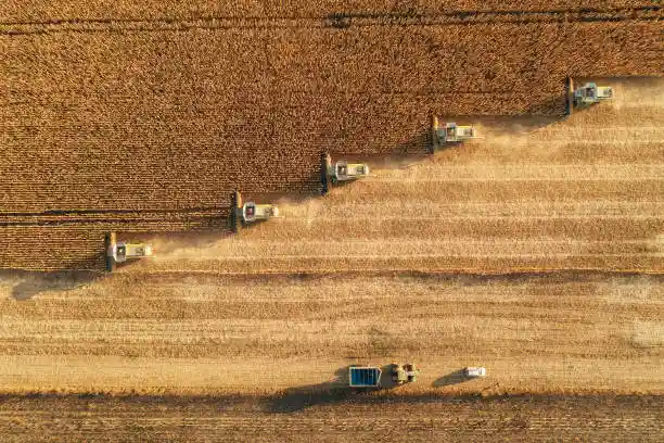
The unloading auger cylinder controls auger deployment and hold position during grain tank discharge — a high-cycle, high-hold-load application.
YD40-245-D5 Combine Unloading Cylinder Specifications: Engineering Logic Behind Each Parameter
Each of the four core dimensions on the YD40-245-D5 reflects a deliberate engineering choice for the auger swing application:
- Bore Ø 40 mm — Matched to Auger Weight and Geometry: The 40 mm bore produces a push force of approximately 18.8 kN at 150 bar (piston area ≈ 12.6 cm²). This is sized for the moment arm load of the auger assembly — the weight of the auger tube, the auger screw, the drive components, and any residual grain load in the tube, acting through the pivot-to-cylinder attachment distance. A 40 mm bore is sufficient for this load without introducing excessive force that would make auger swing control difficult to regulate through the combine’s hydraulic flow control valve.
- Rod Ø 25 mm — Tension-Dominant Loading: The auger swing cylinder mounts in a geometry where the retraction stroke (pulling the auger back to transport position) works against the auger weight and pivot friction simultaneously. The pull force on the 25 mm rod (annulus area ≈ 7.5 cm² less than piston area) is approximately 17.6 kN at 150 bar — adequate for retraction against typical auger assembly weights of 150–250 kg acting through the lever geometry. The rod operates well within its column buckling safety factor across the 245 mm stroke.
- Stroke 245 mm — Full Auger Sweep Arc: The 245 mm stroke translates to the angular travel of the auger from transport fold to maximum operating offset. On most combine platforms using this cylinder, the auger sweeps approximately 90–105° from centreline to operating position. The linkage geometry converts the 245 mm linear cylinder travel into this angular arc, with the mechanical advantage changing across the sweep to maintain controlled force delivery throughout.
- Closed Length 475 mm — Pivot Geometry Constraint: The 475 mm pin-centre closed length determines where the cylinder mounts on the machine frame relative to the auger pivot. This geometry defines the starting angle of the cylinder relative to the auger pivot arm — a parameter that affects both the force available at the beginning of the swing (where the mechanical advantage is typically lowest) and the cylinder’s orientation at full extension, where it must still maintain controlled force without exceeding its side-load tolerance at the gland.
The D5 suffix in the model designation indicates a specific end-cap or port configuration variant within the YD40-245 family. If you are replacing this cylinder, verify the D5 variant is specified — other variants in the YD40-245 series may have different port locations or clevis configurations that are not directly interchangeable with D5 mounting hardware.
Hydraulic Cylinder for Combine Grain Tank Auger Swing: Seal Engineering and Vibration Fatigue Management
The auger swing cylinder experiences a loading pattern that is different from both the continuous-cycling lift cylinders and the static-hold steering cylinder. It cycles a moderate number of times per day, but during each hold phase it sustains a constant eccentric load (the auger hanging at an angle, with its weight acting on the cylinder through the pivot linkage) while simultaneously absorbing vibration energy from the running auger. This combination — sustained eccentric hold plus vibration — is particularly demanding on the pin bore and clevis interface.
At the pin bore interfaces, fretting corrosion is the primary long-term wear mechanism. When a heavily loaded pin joint vibrates, the microscopic relative motion between pin and bore surface removes oxide film, exposing bare metal that immediately re-oxidises, with the oxide then being worn away again. The result is a progressive dimensional increase in the pin bore and a matching degradation of the pin surface — observable as reddish-brown fretting debris around the pin bore opening. On the YD40-245-D5, pin bores are machined to H7 tolerance (the tightest standard bore tolerance for pin joints) with a surface finish of Ra ≤ 1.6 µm at the bore contact surface to minimise the micro-displacement amplitude that drives fretting.
The barrel-to-end-cap joint is welded in the standard configuration and subjected to fillet weld inspection to verify full penetration — partial-penetration welds in this joint location are susceptible to fatigue crack initiation at the weld toe under the vibration loading described above. Hydrostatic proof testing after welding confirms joint integrity, but weld quality is the primary control.
The piston seal on the YD40-245-D5 uses a polyurethane primary seal with a double-lipped design. The outer lip maintains primary pressure hold; the inner lip manages any micro-leakage past the outer lip, directing it back to the high-pressure side rather than allowing it to accumulate between the piston faces — a design that extends service life in hold-under-load applications by reducing the cumulative volume of fluid that bypasses the primary seal before it is noticed as drift.
The chrome rod (25 mm diameter, ≥ 20 µm chrome, ≥ 850 HV) is polished to Ra ≤ 0.2 µm at the rod seal contact zone. Auger cylinders on combines operating in grain harvest conditions encounter both chaff dust and grain dust in the micro-particulate range — the dust wiper on the rod gland is a critical first-line defence, and its effectiveness depends on the rod surface finish being smooth enough to maintain a tight wiper lip contact without excessive friction.
Combine Unloading Auger Cylinder 40mm Bore Replacement: Field Service Guidance
Auger cylinder failures typically become apparent during unloading operations — the most inconvenient possible time, since the grain tank is full and the trailer is alongside. Recognising the early warning signs before an in-field failure occurs allows a planned workshop replacement rather than an emergency field repair:
- Auger drift during unloading: The auger gradually moves away from its set position under load, requiring the operator to re-extend the cylinder periodically to maintain the discharge point over the trailer. This indicates piston seal bypass developing before catastrophic seal failure. The cylinder is still functional but is approaching end of service life — replacement before the following harvest season is the appropriate action.
- Slow auger deployment or failure to reach full extension: Can indicate a partially blocked port, low system pressure, or a cylinder with internal damage causing excessive friction. If the machine’s other cylinders respond normally, the cylinder itself is the most likely cause. Check for external damage to the barrel or rod before assuming internal failure.
- Visible rod gland leakage: External seal failure, as with other cylinder types. Note whether the leakage appears at the gland (rod seal) or at the barrel-end-cap joint (weld or thread joint failure). Gland leakage is the more common failure and the more straightforward repair.
- Pin bore rattle or excessive play at the pivot: Indicates fretting wear at the pin joint. This is not a cylinder failure per se — the pin and bore on the machine bracket may be the worn component — but if the cylinder pin bore is the worn part, a replacement cylinder with new pin bore geometry resolves it.
Pre-season inspection of the auger cylinder — checking for pin bore play, rod surface condition, and a simple pressure hold test (extend cylinder, isolate the ports, observe for position drift over 5 minutes) — identifies failing cylinders before they fail during harvest. This inspection adds less than 30 minutes to a pre-season service and eliminates the risk of a harvest-stopping auger failure at the worst possible moment.
Supply and Stocking: Combine Grain Tank Cylinder Procurement for Distributors and Workshops
The YD40-245-D5 is a mid-volume replacement part for distributors serving combines common across Southeast Asia, South Asia, and Eastern European grain markets. Stocking recommendations and supply logistics:
- Stock level guidance: For distributors serving 20+ combines using this model, a minimum holding of 6–10 pcs before harvest season is appropriate. The D5 variant specificity means cross-substitution from other YD40-245 variants is not straightforward — being out of stock during harvest means a multi-week wait if the cylinder is not pre-positioned locally.
- Lead time from factory: Standard production lead time 15–20 working days ex-works for quantities up to 50 pcs. Rush orders for 1–5 pcs (air freight urgent) can be dispatched within 5–7 working days in most cases — contact us to confirm current production scheduling.
- Packaging: Each cylinder is individually foam-wrapped and boxed with model, bore, stroke, and mounting length marked on the exterior. Carton dimensions approximately 550 × 100 × 100 mm, weight approximately 2.5–3 kg per piece.
- Documentation: Commercial invoice, packing list, certificate of origin, material certificate, and hydrostatic test record available with each shipment. For distributors with ISO quality management systems, we can supply dimensional inspection reports on request.
We can also work with distributors to confirm cross-reference compatibility with OEM part numbers from the combine manufacturers your customer base operates, eliminating sourcing uncertainty before your first stocking order.
Complete Technical Specifications — YD40-245-D5
| Parameter | Value |
|---|---|
| Model Number | YD40-245-D5 |
| Product Type | Unloading Auger Cylinder (卸粮油缸) |
| Bore Diameter | 40 mm |
| Rod Diameter | 25 mm |
| Stroke | 245 mm |
| Closed Length (C–C) | 475 mm |
| Rod-to-Bore Ratio | 62.5% |
| Cylinder Type | Double-acting, hold-under-load specification |
| Piston Seal | Double-lipped PU — hold-under-vibration design |
| Rod Seal | PU primary lip seal + dust exclusion wiper |
| Rod Surface | Hard chrome ≥ 20 µm · ≥ 850 HV · Ra ≤ 0.2 µm |
| Pin Bore Tolerance | H7 — fretting fatigue managed specification |
| Barrel-End Joint | Full-penetration weld, inspected + proof tested |
| Application | Combine grain tank unloading auger swing & hold |
| Packaging | Individual foam-lined carton, ~550 × 100 × 100 mm |
| MOQ | 1 pc (sample); stock orders from 6 pcs; annual pre-season supply available |
Pre-Season Stock the YD40-245-D5 — Before Harvest Demand Peaks
Auger cylinder failures during active harvest are high-cost events — not because the part is expensive, but because the machine stops earning while you wait for parts. Contact us now to lock in pre-season pricing, confirm D5 variant compatibility with your machine platform, and arrange documentation for your quality management system.