الوصف
YM4P.83.06a · Corn Harvester Series
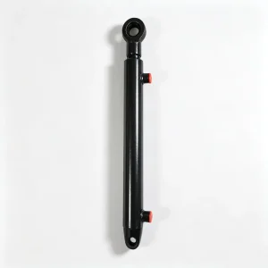
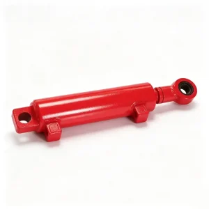
Grain Tank Lift Cylinder — 1425 mm Long-Stroke Precision Lifting for Corn Harvester Grain Frame Systems
Part No. YM4P.83.06a | Bore: 63 mm | Rod: 40 mm | Stroke: 1425 mm | C/C: 1780 mm
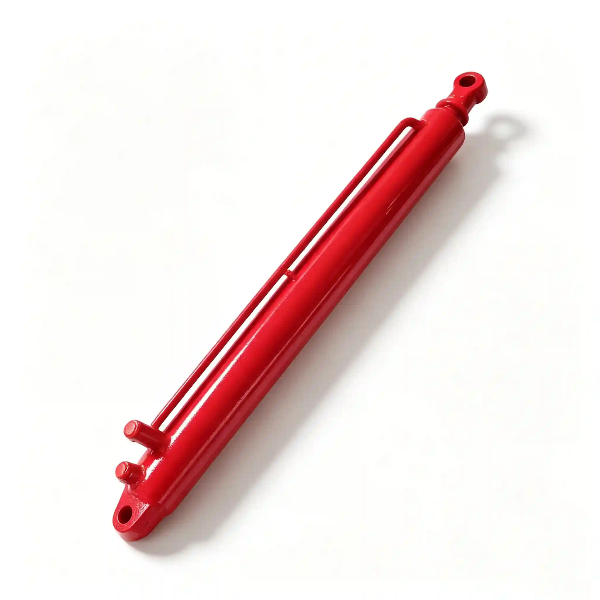
YM4P.83.06a Grain Tank Lift Cylinder
ال YM4P.83.06a grain tank lift cylinder is the longest-stroke hydraulic actuator in the YM4P corn harvester family — with a 1425 mm stroke and a 1780 mm center-to-center mounting distance, it operates at a scale that immediately separates it from the rest of the cylinder set. Its function is to raise and support the grain tank frame assembly, positioning the unloading auger and grain elevator structure into the working or transport configuration. At full extension, it is simultaneously a lifting actuator and a structural support column, carrying the combined weight of the grain frame and its contents against the machine frame.
Long-stroke hydraulic cylinders in this class introduce engineering challenges that compact actuators never face: rod column buckling, dynamic lateral deflection at mid-stroke, oil volume and flow-rate requirements, and the critical importance of a correctly specified rod wiper system to exclude the wide variety of contaminants encountered as a 1425 mm rod surface cycles in and out of exposure over a harvest season.
Long Stroke Hydraulic Cylinder Specifications — 63mm Bore, 40mm Rod, 1425mm Stroke Full Parameter Table
| Parameter | Value | Engineering Note |
|---|---|---|
| Bore Diameter (D) | 63 mm | At 160 bar, push force ≈ 49.8 kN. Sized to lift a fully loaded grain elevator frame (estimated 300–500 kg structure) with adequate flow-rate margin on the machine’s hydraulic circuit. |
| Rod Diameter (d) | 40 mm | Rod/bore ratio = 0.635. At 1425 mm exposed length, buckling analysis is mandatory — see Euler column calculation below. This ratio is the result of optimising between column stability, annular flow volume, and rod mass. |
| Stroke (L) | 1425 mm | The longest stroke in this harvester’s cylinder set. Full extension raises the grain tank frame from transport to operating/unloading position. Volume of oil to extend: π/4 × 0.063² × 1.425 ≈ 4.44 litres — a significant draw on circuit volume. |
| Mounting Distance (C/C) | 1780 mm | C/C retracted: 1780 mm. Extended: 3205 mm. These are the two critical dimensions for frame bracket design and transport height compliance. |
| Rated Working Pressure | 160 bar (2,320 psi) | Standard agricultural circuit. At this pressure, the cylinder generates sufficient force to lift and hold the grain tank frame against gravity and wind loading in working position. |
| Peak / Surge Pressure | 210 bar (3,045 psi) | Moderate surge rating vs. engagement-type cylinders — grain tank lift is a slow-travel, gravity-assisted cycle with minimal hydraulic shock. Tube wall calculated for 4:1 safety factor at surge pressure. |
| Rod Surface Treatment | Hard chrome, 30–35 µm | Thicker chrome spec than short-stroke cylinders: on a 1425 mm exposed rod, even a 50 mm corroded zone will score the wiper on every retract cycle. Minimum 30 µm chrome across full rod length, verified by eddy-current inspection on production batches. |
| Wiper / Seal System | Triple-element gland pack | Outer scraper + intermediate PU wiper + inner rod seal. Three-element stack is standard practice for long-stroke outdoor cylinders where a single wiper cannot exclude fine grit accumulated over a full stroke length. |
| Cylinder Tube Wall | 10 mm (E355 seamless) | Heavier wall than short-stroke cylinders — required to maintain tube straightness over the 1780 mm retracted length and to provide mounting-bracket weld area at both ends. |
| Internal Leakage | ≤ 5 cc/min at rated pressure | Slightly relaxed vs. header lift cylinder — positional drift during a grain unloading cycle is acceptable within ±10 mm. Stricter sealing on the rod side prevents external leakage contaminating grain. |
Engineering Reference · Force, Volume & Buckling Analysis
Push Force (extend — frame raise): F = 160 bar × π/4 × (0.063)² ≈ 49,764 N (49.8 kN)
Pull Force (retract — frame lower): F = 160 bar × π/4 × (0.063² − 0.040²) ≈ 29,656 N (29.7 kN)
Oil volume to full extend: V = π/4 × 0.063² × 1.425 ≈ 4.44 litres (bore side). At a typical harvester circuit flow rate of 20 L/min, full stroke extension takes approximately 13 seconds — a design-appropriate raise speed for a grain tank frame.
Rod Buckling (Euler, pinned-pinned condition):
Second moment of area for Ø40 mm solid rod: I = π × 40⁴ / 64 = 125,664 mm⁴. Euler critical load (steel, E = 210 GPa, effective length = 1425 mm, both ends pinned): F_cr = π² × 210,000 × 125,664 / 1425² ≈ 128,000 N (128 kN).
With a working push force of 49.8 kN, the buckling safety factor is 2.57:1 — above the 2.5:1 minimum recommended by ISO 6020/2 for pin-mounted cylinders. This validates the 40 mm rod as correctly specified. A smaller 32 mm rod (common in generic long-stroke cylinders) would yield F_cr ≈ 53 kN and a safety factor of only 1.06 — effectively at the margin of buckling failure under operating load.

The grain tank lift cylinder operates across the machine’s full vertical range — from transport to elevated unloading position
Grain Tank Lift Cylinder 1425mm Stroke OEM Design — Engineering Challenges Unique to Long-Travel Actuators
A 1425 mm stroke cylinder is not simply a scaled-up version of a compact actuator. Every major design parameter changes non-linearly with stroke length. Procurement teams sourcing this type of component for the first time — or switching suppliers — need to understand four specific challenges that are directly addressed in the YM4P.83.06a specification:
① Rod Column Buckling
At 1425 mm exposed length, an under-specified rod will buckle under its own rated push force — not as a sudden fracture, but as a gradual lateral bow that drives the rod off-centre in the gland, scoring the bore and cutting through the rod seal within weeks. The 40 mm rod is the calculated minimum to maintain a 2.5:1 Euler buckling safety factor. Any supplier quoting a 32 mm or 35 mm rod on this envelope is offering a compromised product. Verify the buckling calculation before accepting an alternative specification.
② Rod Surface Contamination Over Full Stroke Length
On a 110 mm stroke cylinder, a single wiper can clean the entire rod surface on each cycle. On a 1425 mm stroke, the rod surface that is exposed when extended must travel back through the gland seal pack over a period of 13 seconds. In a corn harvest environment — with fine chaff, soil dust, and morning moisture — a 1425 mm rod accumulates contamination that a single wiper cannot reliably exclude. The triple-element gland pack (outer steel scraper, intermediate PU wiper, inner PU rod seal) is the correctly specified arrangement for this duty. Single-wiper gland designs sourced as cheaper alternatives routinely show internal contamination after the first season, destroying piston seals and contaminating the machine’s hydraulic fluid.
③ Tube Straightness and Alignment
A cylinder tube of 1780 mm closed length must maintain bore concentricity within 0.05 mm/m over its full length for the piston to travel without metal-to-metal side loading. This requires precision honing after straightness verification — not standard in lower-cost production. The YM4P.83.06a tube is straightness-checked after honing using a mandrel gauge, and any tube exceeding 0.1 mm total runout is rejected. This step adds process time but eliminates the failure mode of a “tight” spot mid-stroke that accelerates PTFE guide ring wear and piston seal failure.
④ Hydraulic Oil Volume and Thermal Implications
Extending this cylinder to full stroke displaces 4.44 litres of oil into the bore-side circuit. On a machine with a 40-litre hydraulic reservoir, this is an 11% reservoir drawdown in a single actuator stroke. If the machine is simultaneously operating other hydraulic functions (steering, feeder house), the combined draw can cause transient circuit pressure drop and oil temperature rise. This is not a cylinder design fault — it is a system-level fact that integrators must account for when sizing the hydraulic pump, reservoir, and cooler on machines using this cylinder.
63mm Bore OEM Cylinder Construction Standards — Materials, Finishing, and Quality Control
Cylinder Tube
E355 cold-drawn seamless steel, 63 mm bore × 10 mm wall. Honed to Ra ≤ 0.4 µm after straightness verification. External finish: zinc phosphate + two-coat polyurethane, 80 µm DFT minimum, 500-hour salt spray tested. Tube ends machined for full-penetration butt weld to end caps.
قضيب الكروم
Ck45 steel, ground and polished to Ra ≤ 0.2 µm. Hard chrome 30–35 µm, HV 800+, eddy-current inspected for chrome thickness uniformity across full 1425 mm rod length. Post-chrome ground to h6 tolerance. Rod straightness: ≤ 0.3 mm total over full length (tighter than ISO default for this length class).
Gland Seal Pack
Triple-element: (1) steel-reinforced scraper for coarse debris exclusion, (2) polyurethane intermediate wiper rated to 0.5 MPa back-pressure, (3) double-lip PU rod seal. Bronze guide bush in gland. Separate seal kit catalogued for field replacement — all three elements replaced as a set.
Piston Assembly
Cast iron piston, double bronze guide rings (widened bearing surface for long-stroke lateral load management). Primary piston seal: PU quad-ring + PTFE energised backup. Piston-to-rod connection: fine-thread castellated nut with split-pin locking — no adhesive bonding.
End Fixings
Both ends: clevis-type, Ø32 mm pin bore, sintered bronze self-lubricating bush, grease nipple. The larger pin diameter (vs. shorter cylinders) reflects the higher bending moment at the pin on a 1780 mm span. Clevis walls minimum 16 mm thickness, machined from structural steel plate.
Quality Control
Each cylinder: (1) hydrostatic proof test at 250 bar for 60 seconds — zero leakage, zero permanent deformation. (2) Full-stroke cycle test: 5 cycles under rated load, leakage checked on both port sides. (3) Dimensional audit: C/C, stroke, pin bore, port position. Test records retained per batch and available to OEM customers on request.

The grain tank frame must reach and hold maximum height reliably on every unloading cycle throughout harvest
Service Life and Field Maintenance — Long-Stroke Cylinder Inspection Schedule for Corn Harvester OEM Operators
A 1425 mm stroke cylinder has a larger exposed rod surface, more oil volume under pressure, and a longer seal travel per cycle than any other cylinder on this machine. A structured inspection schedule significantly extends service intervals and prevents the unpredictable in-season failures that are costly to repair in the field.
| Interval | Inspection / Action | Failure Mode Prevented |
|---|---|---|
| Pre-season | Inspect full rod surface for chrome pitting or rust spotting. Grease all pin bushes. Check port fittings for corrosion seizing. Cycle cylinder 3× under no-load, check for smooth travel and zero external leakage. | Chrome corrosion → wiper seal scoring; seized fittings causing hose damage on first pressurisation. |
| Every 50 operating hours | Inspect rod seal gland for oil weeping. Check pin bush for play (replace if >0.5 mm radial clearance). Wipe rod surface and inspect chrome under light for early pitting. | External rod seal leakage → contamination of grain elevator components; pin wear → side-load scoring of rod. |
| Annual / End of season | Replace complete gland seal kit (all three elements). Replace pin bushes. Clean and re-grease all pivot points. Check hydraulic fluid for particulate contamination (patch test or cleanliness analysis if available). | Cumulative seal fatigue; particulate contamination propagating to pump and control valves. |
| At any oil weeping | Do not defer — replace rod seal kit immediately. Check chrome condition before re-sealing. If chrome shows pitting deeper than 0.3 mm, rod reconditioning or replacement is required before fitting new seals. | Escalating leakage → internal contamination → piston seal failure → uncontrolled frame descent risk. |
Combine Harvester Grain Tank Frame Lift Cylinder — Custom Stroke and OEM Configuration Options
Long-stroke cylinders are inherently more platform-specific than compact actuators — mounting distances, stroke lengths, and pin sizes vary widely between machine families. Custom configurations are available on the following parameters:
- Stroke: 1100–1600 mm within the current rod and tube design family. Strokes above 1600 mm require individual engineering review for buckling and tube straightness feasibility.
- Mounting distance (C/C): Adjustable to specification. Provide retracted C/C and extended C/C (or stroke) — one determines the other. Both are required for bracket compatibility sign-off.
- Rod diameter: 40 mm standard. 45 mm or 50 mm available for higher-load platforms or increased buckling margin — recommended for heavy grain tank assemblies above 600 kg or platforms with significant lateral loading on the cylinder.
- Port standard and position: BSP G1/2″, SAE ORB #8, NPT 1/2″. Port position (bottom-of-gland vs. side-of-tube) configurable for routing constraints.
- Cushioning: Adjustable end-of-stroke cushion on bore-side port available for smooth deceleration at full extension — prevents frame impact loading on the cylinder mounting bracket.
- Seal material: Standard PU/PTFE. FKM (Viton) available for biodegradable HETG fluid requirements. NBR available as a lower-cost alternative for controlled-environment storage applications.
- OEM identification: Part number engraving, custom colour coding, and private-label documentation available at MOQ ≥ 20 pcs (lower MOQ threshold applies to long-stroke cylinders due to higher unit value).
All custom long-stroke configurations are provided with a buckling calculation report, 2D dimensional drawing for bracket review, and STEP file on request — before production confirmation. Lead time: 25–40 business days ex-works for custom stroke configurations; stock dimensions ship within 10 business days.
Ready to Specify or Procure?
Request Buckling Report, CAD Drawings, or Custom Long-Stroke Engineering Review
Long-stroke cylinder procurement requires more technical pre-work than standard actuators. Our engineering team provides buckling safety calculations, dimensional drawings, and full 3D STEP files before order confirmation — standard for all OEM and integrator enquiries.