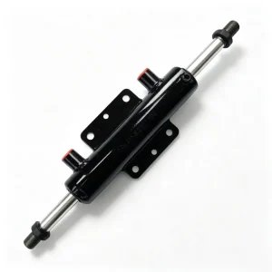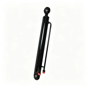
विवरण
Hydraulic Cylinders › Stick / Arm Cylinders › Mini & Compact Excavators
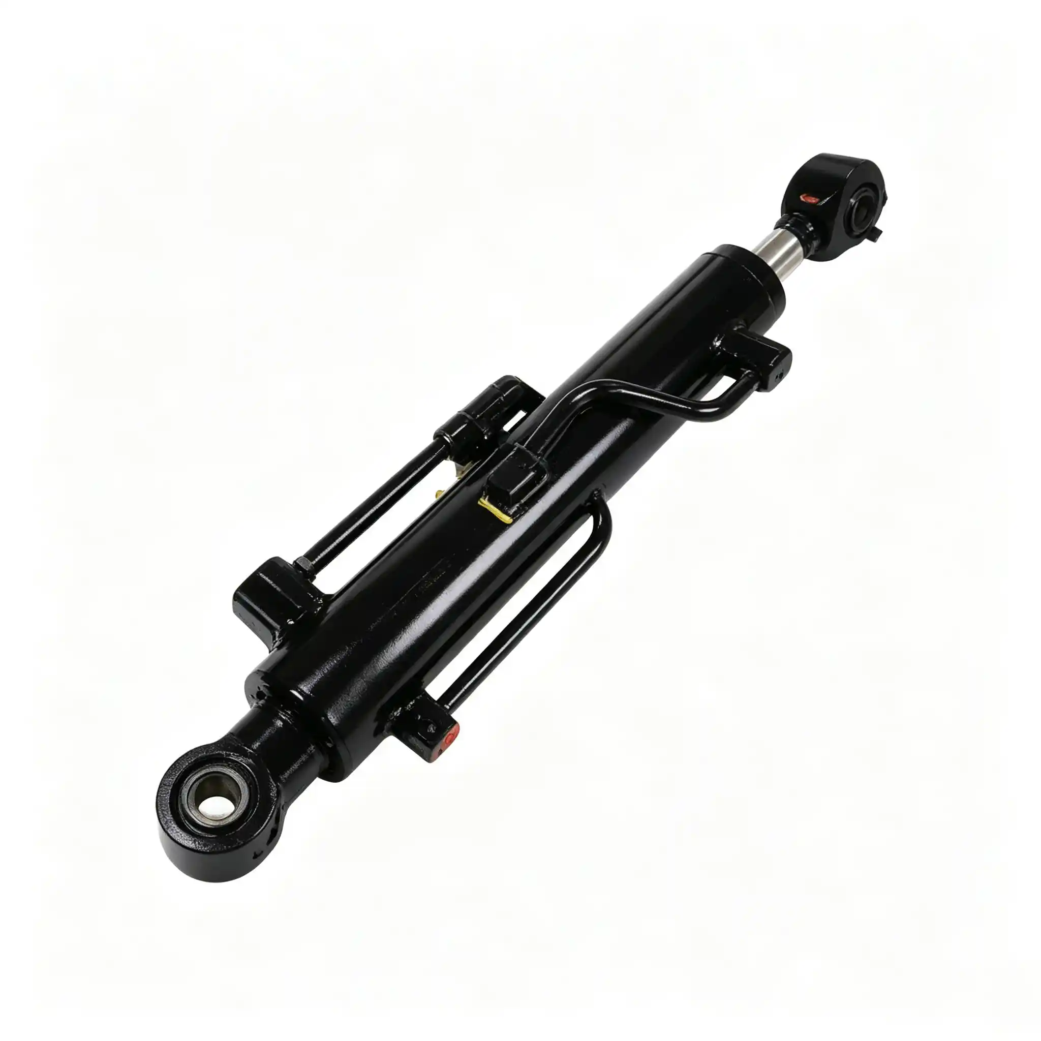
CSYG2075B Stick Cylinder for Mini & Compact Excavators
A 50 mm bore, 30 mm rod, 325 mm stroke stick cylinder engineered for the highest push-pull cycle frequency of any position on the excavator — where seal fatigue accumulates faster than on any other cylinder, and digging rhythm directly governs machine productivity.
Why the Stick Cylinder Accumulates Seal Wear Faster Than Any Other Cylinder on a Mini Excavator
Count the hydraulic cylinder movements in one complete excavation cycle on a compact excavator — swing out, lower boom, extend stick, curl bucket, crowd stick back, raise boom, swing back, dump. Of those movements, the stick cylinder makes two full directional reversals: one extension into the cut and one retraction to complete the crowd. At a typical digging rhythm of 14–18 cycles per minute during sustained trench work, the stick cylinder executes 1,700–2,200 full push-pull direction changes per hour. The boom cylinder, by comparison, makes one reversal per cycle and spends a significant portion of its time static under load. The bucket cylinder reverses similarly to the stick, but over a shorter stroke. The stick cylinder, with its 325 mm stroke and continuous dynamic load profile, accumulates seal-face sliding distance faster than any other position on the machine.

This operating reality has a direct consequence for procurement decisions: the stick cylinder’s rod seal, piston seal, and wiper seal are the components most likely to reach their wear limit before any other cylinder on the machine. A stick cylinder that begins bypassing internally — allowing hydraulic fluid to migrate past the piston seal — causes the arm to drift forward under its own weight during the swing phase, disrupting the operator’s ability to maintain a clean, consistent digging arc. Even a 5–8% reduction in available push force from a partially bypassed piston seal is perceptible to an experienced operator as reduced arm crowd authority in hard ground.
The CSYG2075B is configured for this duty: 50 mm bore for adequate force margins in both push and pull directions, a 30 mm rod sized for the bending moments of the arm’s working geometry, and a 325 mm stroke that delivers the arm reach arc required for productive digging depth in the 1.5–5 tonne machine class. The seal package prioritises dynamic cycling endurance over static holding performance — the inverse of the specification priority applied to boom cylinders.
50 mm Bore / 30 mm Rod / 325 mm Stroke: What Each Dimension Controls in Arm Digging Performance
Parameters interpreted for procurement engineers, fleet technicians, and equipment distributors
| Parameter | Value | Engineering Significance |
|---|---|---|
| Bore Diameter | 50 mm | Piston area ≈ 19.6 cm². Push force ≈ 39.3 kN at 20 MPa. Drives arm crowd force — the primary digging input. Pull force (rod retraction) ≈ 25.1 kN, governing arm extension speed under load |
| Rod Diameter | 30 mm | At 325 mm extended stroke, rod slenderness ratio remains within safe Euler buckling limits for typical arm pivot geometry. The 30 mm diameter provides the cross-section needed to resist the bending moments introduced by off-axis arm crowd in sloped trench work |
| Stroke | 325 mm | Controls the angular sweep of the arm pivot — determining the difference between maximum reach and maximum dig depth positions. Longer than the boom stroke on the same machine class, reflecting the arm’s greater arc requirement. Also means more rod-seal sliding distance per cycle than boom or bucket |
| Installation Distance | 535 mm | Pin-to-pin retracted length. Must match within ±1 mm — an oversized installation distance pre-loads the arm linkage in extension, preventing full retraction and stressing hinge pins from day one of service |
| Application Position | Stick / Arm (Crowd) | Highest continuous cycle frequency of all five cylinders. Seal endurance under dynamic cycling — not static holding strength — is the governing specification criterion |
| Machine Class | Mini & Compact, 1.5–5 t | Geometry-matched for rubber-tracked mini excavators, short-radius compact machines, and agricultural diggers operating at this pivot-to-pivot arm dimension |
Why the Stick Stroke Is Longer Than the Boom Stroke on the Same Machine — and What That Means for Seal Life
On most compact excavators in the 2–4 tonne class, the boom cylinder stroke is 270–300 mm, while the stick cylinder stroke is 310–340 mm. This difference reflects the geometric role of each component: the boom pivots through a modest arc to set working height, while the arm sweeps a larger arc to cover the full digging radius from maximum reach to minimum curl. A longer stroke means more rod exposed and retracted per cycle, which means more wiper seal contact distance per hour and more rod-seal lip travel per hour. Over 1,000 operating hours — a typical service interval for a well-maintained mini excavator — the stick cylinder rod seal accumulates roughly 30–35% more sliding distance than the boom cylinder seal in identical operation. This is the quantitative basis for prioritising seal quality in the stick cylinder specification above all other positions.
The bore-to-rod ratio on the CSYG2075B is 50:30 — a ratio of 1.67:1. This is deliberately more conservative (larger rod relative to bore) than some budget stick cylinder designs that use a 40 mm bore with a 25 mm rod. The larger rod diameter provides two tangible benefits: higher pull force on the extension stroke (which governs how quickly the arm can be repositioned for the next digging pass), and greater resistance to the bending loads imposed when the machine digs at an angle to the trench wall or on sloped ground.
Seal Endurance Engineering: How the CSYG2075B Is Built for 2,000+ Hours of Continuous Push-Pull Cycling
Piston Rod Metallurgy: Induction Hardening Gradient for Fatigue Resistance
The 30 mm rod is machined from 45# medium-carbon steel (SAE 1045 equivalent), selected for its fatigue response under fully reversed bending loads — the condition imposed every time the arm direction reverses under load. High-frequency induction hardening creates a surface layer of 1.5–2.5 mm depth at HRC 54–58, with the core remaining at HRC 28–32. The fatigue significance of this gradient is specifically relevant to the stick cylinder: a rod that cycles 2,200 times per hour experiences more cumulative bending-fatigue cycles per operating hour than any other cylinder rod on the machine. A fully through-hardened rod would have higher surface hardness but severely reduced fatigue ductility — it would be more prone to brittle fracture under the repeated bending moments from off-axis digging. The induction-hardened surface / ductile core structure is the correct material response to this loading regime.
Hard Chrome Plating: Oil-Film Retention Is the Key Parameter for Dynamic Cycling
A 25–40 μm hard chrome layer is applied after induction hardening, achieving HV 900–1,000 at the rod surface, then ground and polished to Ra 0.2–0.4 μm. For the stick cylinder, the most functionally important property of this chrome finish is not hardness — it is oil-film retention. The controlled micro-porosity of the electroplated chrome surface holds a thin hydraulic-oil film in suspension between rod seal contacts. During the direction-reversal moment of each digging cycle — when the rod momentarily decelerates to zero velocity before reversing — the seal lip is in full contact with a stationary rod surface. Without an oil film at this interface, stick-slip friction causes the seal lip to momentarily adhere to the rod, then release as motion resumes, generating a microscopic tearing stress at the seal lip root. Over tens of thousands of reversals, this stick-slip mechanism is a primary driver of premature seal lip cracking — a failure mode distinct from abrasive wear and not visible until the seal begins to weep.
The Ra 0.2–0.4 μm finish on the CSYG2075B rod is tighter than the Ra 0.4–0.8 μm that some budget replacement cylinders specify. This finer finish reduces the amplitude of the surface texture that the seal lip must deform around to maintain contact, lowering the contact stress at each asperity and extending the elastic life of the polyurethane lip material across repeated thermal and mechanical cycles.
Dynamic Seal Stack: Specification Priorities for High-Cycle Arm Service
The primary rod seal is a polyurethane U-cup of the formulation used in NOK and SKF service kits for this bore size. Polyurethane’s tensile strength (typically 35–45 MPa) is approximately three times that of standard nitrile, and its abrasion resistance is measurably higher under the sliding friction conditions of dynamic rod sealing. For the stick cylinder’s operating cycle count, polyurethane’s fatigue endurance under repeated deformation is the decisive material advantage — not simply its resistance to hydraulic fluid degradation.
The piston seal uses a step-cut PTFE or polyurethane U-cup configuration. Internal bypass at the piston — the mechanism that causes arm drift — is the failure mode most immediately felt by the operator as degraded digging performance. The piston seal geometry creates a pressure-energised contact profile: as system pressure increases during a hard digging pass, the seal lip contact force increases proportionally, maintaining zero bypass under precisely the conditions when bypass would be most operationally disruptive.
- Wiper seal: Single or dual-lip polyurethane wiper at the rod gland, selected by contamination exposure level. The stick cylinder position is less directly exposed than the bucket cylinder but faces more cycles per hour, requiring a wiper material that resists fatigue cracking at the lip root as much as abrasive wear at the lip face.
- Guide bands: Fibre-reinforced PTFE guide rings at piston and rod positions carry lateral loads from off-axis digging without metal-to-barrel contact, preventing the bore scoring that would otherwise accelerate piston seal bypass.
- O-ring backup elements: High-ACN nitrile O-rings at static gland interfaces maintain compression set resistance across the oil temperature range of 20–80°C encountered in continuous high-cycle operation.
- Seal kit availability: The CSYG2075B seal stack is available as a separately purchasable reseal kit, enabling field service without replacing the complete cylinder — a cost structure that matches the stick cylinder’s shorter reseal interval relative to other positions.
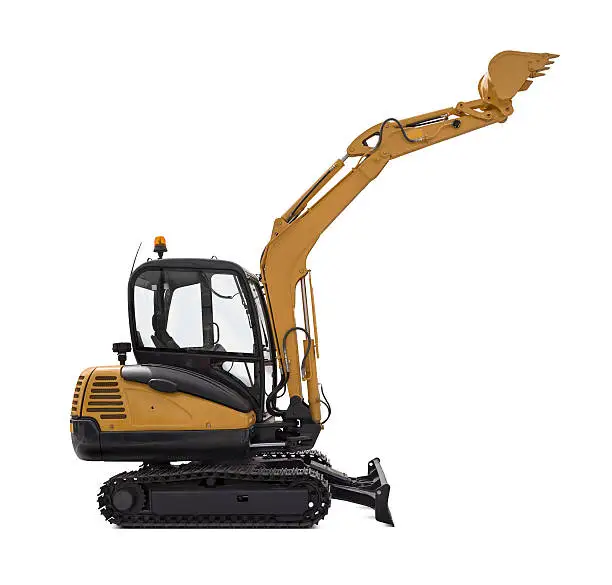
Sustained trench excavation: the operating condition where stick cylinder cycle frequency peaks and seal fatigue accumulates most rapidly
Arm Crowd Force, Direction-Reversal Mechanics, and Dig-Cycle Continuity: The Three Performance Axes of the Stick Cylinder
Arm Crowd Force and Its Direct Relationship to Digging Productivity
Arm crowd force — the horizontal thrust at the stick tip when the arm pulls toward the machine — is the primary variable that determines how aggressively the bucket can be pulled through compacted soil or root-bound ground in a single pass. At 20 MPa and a 50 mm bore, the CSYG2075B delivers 39.3 kN of push force on the crowd stroke. Through the arm pivot geometry of a typical compact excavator, this translates to a stick crowd force at the bucket pin of approximately 12–18 kN depending on arm angle — the variable that operators experience as the machine’s ability to maintain cutting speed through a hard layer without stalling the hydraulic circuit.
Equally important is the pull force on the retraction (arm extension) stroke: 25.1 kN at 20 MPa from the 30 mm rod annulus. This force governs how quickly the arm can be repositioned to the next dig point after dumping. In a high-productivity digging cycle, the extension stroke is not a dead-time pause — it must reposition the arm against gravity and inertia within the available cycle time. An undersized rod annulus area (as found in budget cylinders with 25 mm rods) produces a 20–25% reduction in retraction force, measurably slowing the repositioning half of each cycle and reducing overall output cycles per hour.
Direction-Reversal Dynamics: The Hydraulic Shock at Each Stroke End
Each time the stick cylinder reaches the end of its stroke and the operator reverses direction, a hydraulic pressure spike occurs as the moving oil column is decelerated. At 14–18 cycles per minute, this produces 28–36 pressure transients per minute at the cylinder ports — events that briefly raise local pressure 10–30% above the nominal system pressure, depending on how abruptly the operator reverses the control lever. These transients are largest at maximum crowd-out (full extension) where arm inertia is highest and gravity assists the motion. Over time, cumulative hydraulic shock loading at the piston seal creates micro-extrusion of seal lip material into the gap between piston and barrel bore — a process that does not cause immediate bypass but progressively reduces the seal’s effective radial interference, accelerating the onset of internal bypass in the medium term.
The CSYG2075B piston seal geometry addresses this through a controlled backup ring configuration that limits lip extrusion into the piston-barrel gap during pressure transients, preserving seal geometry across tens of thousands of reversal cycles. This is a detail that does not appear in cylinder specification sheets but is the difference between a piston seal that maintains bypass-free performance to 1,500 hours and one that begins to drift at 600–800 hours under the same operating conditions.
Push (Crowd) Force
39.3 kN
@ 20 MPa, 50 mm bore
Pull (Extension) Force
25.1 kN
@ 20 MPa, 30 mm rod
Reversal Events/Hour
3,400+
At 17 dig cycles/min sustained trench work
Rod Surface Finish
Ra 0.2–0.4
μm — critical for stick-slip prevention at reversal

Urban confined-site operation: where arm crowd speed and smooth reversal response define the operator’s ability to maintain digging rhythm
Installation Procedure, Compatibility Verification, and Maintenance Schedule Calibrated to Stick Cylinder Cycle Rates
Installation Distance Verification: The Most Commonly Skipped Step
The CSYG2075B’s 535 mm pin-to-pin installation distance must be verified against the machine’s service manual before ordering. This measurement is taken with the cylinder fully retracted (arm at maximum extension position). A replacement cylinder with even 5 mm excess in this dimension will not allow full arm extension without binding the linkage — a condition that is frequently misdiagnosed as a hydraulic flow problem or a valve fault, leading to unnecessary component replacement before the actual cause (installation distance mismatch) is identified. Measure twice, order once.
Port Thread and Hose Connection: Confirming Standards Before Fitting
Mini excavators in the 1.5–5 tonne segment use 3/8″ BSP, G3/8, or metric M18×1.5 port threads on the stick cylinder depending on manufacturer and production year. The CSYG2075B uses standard port sizing for this bore class — confirm the specific thread form of the existing hose end fittings before selecting adapters. Avoid over-torquing port fittings on initial assembly: the cylinder barrel port boss area is the most structurally thin section of the barrel and is disproportionately vulnerable to thread damage from excessive wrench force. Use a calibrated torque wrench and follow the fitting manufacturer’s specification — typically 55–75 Nm for 3/8″ BSP in this bore range.
Maintenance Schedule Calibrated to Stick Cylinder Duty Cycle
- Daily (operator): Inspect the exposed rod surface at end of shift for visible score marks or surface discolouration from contact with foreign objects — stone chips, reinforcing rod ends, or concrete fragments are the common culprits in urban construction. Any score visible to the naked eye should be assessed before the next operating shift: a scored rod left in service accelerates primary seal failure at a non-linear rate.
- 50-hour interval: Grease the arm pivot pins (boom-to-arm and arm-to-bucket) with NLGI #2 EP lithium grease. Worn pivot pin bushings allow angular play in the arm linkage that is directly transmitted to the cylinder rod as lateral load on the rod-guide bearing. Dry bushings at one or both pins produce bending moments that can accelerate rod-seal wear by 40–60% compared to well-greased pivot points.
- 250-hour interval: Perform an internal bypass check: hold the arm crowded fully in under hydraulic pressure, centre the control lever (engine at idle, system at charge pressure), and observe arm movement over 3 minutes. Drift exceeding 20 mm indicates piston seal bypass approaching service threshold. At this cycle frequency, early intervention avoids barrel scoring from prolonged operation with a degraded piston seal.
- 400–600-hour interval: Replace the wiper seal and primary rod seal as a combined service. The stick cylinder’s seal replacement interval is shorter than for the boom cylinder (typically 800–1,200 hours) due to the higher cycle accumulation rate. Scheduling this as a planned maintenance event — rather than a reactive repair after external oil weeping begins — keeps the cylinder serviceable without barrel involvement.
- Hydraulic oil cleanliness: Maintain ISO 4406 cleanliness at 17/15/12 or better. The stick cylinder’s high stroke frequency means a proportionally higher volume of oil passes through the piston seal interface per operating hour compared to other cylinders. Elevated particulate contamination in the oil accelerates piston seal abrasion from the internal side — a failure pathway entirely separate from external wiper seal contamination ingress.
Request a Quote, Technical Drawing, or Volume Pricing for the CSYG2075B
Our technical team holds dimensional drawings, seal-kit breakdowns, and cross-reference tables for the CSYG2075B and 2,000+ related stick cylinder part numbers across the mini and compact excavator segment. Single replacement units, service-parts stocking orders, and OEM supply volumes are all handled with the same response standard.
एक उद्धरण का अनुरोध करें
Provide your machine model, quantity, and destination port. FOB/CIF pricing returned within one business day.
Technical Drawing
Full dimensional drawings (PDF/DWG) and seal-kit parts list available for qualified dealers and fleet procurement accounts.
Custom Specification
Non-standard bore, rod, stroke, port thread, or mounting configuration? Submit existing cylinder dimensions for a custom quotation.
- ✓ MOQ: 1 piece for sample evaluation
- ✓ Seal kits sold separately for field reseal
- ✓ Lead time: 7–15 business days standard
- ✓ 100% pressure-tested to 1.5× rated pressure
- ✓ Payment: T/T, LC at sight
- ✓ Export packing: wooden crate or fumigated pallet
Certificates of conformance and material test reports available for fleet and OEM accounts on request.