विवरण
WPWDKS Worm Drive Speed Reducer Product Overview
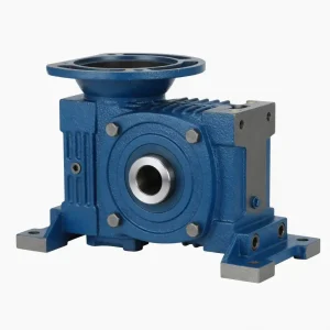
The WPWDKS Worm Drive Speed Reducer is a compact, shaft-mount worm drive speed reducer built around a die-cast HT200 iron housing. Unlike fabricated-steel enclosures, the cast iron structure provides inherent vibration damping and natural heat dissipation — allowing continuous-duty cycles in ambient temperatures up to 40°C on sizes ≤135 without auxiliary cooling.
As part of the WP series worm gearbox family, the WPWDKS ships across 12 frame sizes (40 through 250 mm center distance) with eight selectable ratios from 1:10 to 1:60. The worm wheel is machined from tin-bronze alloy (Copper-10-3#), paired against a 20CrMnTi steel worm that is carburized and quenched to 56–62 HRC — a combination that keeps the softer bronze wheel from scoring even under cyclic load reversals.
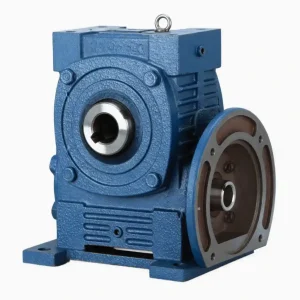
The worm wheel reducer accepts direct IEC flange mounting (56B14 through 80B14 and beyond) and is compatible with standard AC motors, VFDs, brake motors, and continuously variable drives. A double-stage configuration — two WPWDKS units in series — extends the effective output ratio well beyond 1:60 for extremely low-speed drive requirements.

Technical Specifications of WPWDKS Worm Drive Speed Reducer

| Parameter | Specification |
|---|---|
| Model | WPWDKS (Sizes 40–250) |
| Gear Ratio Options | 1:10 · 1:15 · 1:20 · 1:25 · 1:30 · 1:40 · 1:50 · 1:60 |
| Housing Material | HT200 Die-Cast Grey Iron |
| Worm Wheel Material | Tin-Bronze Alloy Copper-10-3# |
| Worm Material & Treatment | 20CrMnTi steel — carburized & quenched; surface hardness 56–62 HRC |
| Output Shaft Material | 45# Chromium Steel |
| Input Power Range | 0.12 kW – 15 kW |
| IEC Flanges Supported | 56B14 · 63B14 · 63B5 · 71B14 · 80B14 + custom |
| Lubricant Compatibility | ISO VG 220/320 Mineral Oil or PAO Synthetic |
| Standard Finish Color | Blue / Silver — custom on request |
| Packing | Carton + wooden case |
| Warranty | 12 months from shipment date |
| Suitable Industries | Food processing · Ceramics · Chemicals · Packaging · Textile dyeing · Woodworking · Glass |
▼ Dimensional & Power Data by Frame Size (mm / kW / kg)
| Size | Power (kW) | Ratio | A | AB | B | AC | BC | HL | H | LA | LB | LC | S | W×Y | Wt (kg) |
|---|---|---|---|---|---|---|---|---|---|---|---|---|---|---|---|
| 40 | 0.12 | 1/5–1/60 | 135 | 75 | 85 | 95 | 61 | 45 | 135 | 115 | 95 | 140 | 16 | 6×18.8 | 5 |
| 50 | 0.18 | 1/5–1/60 | 151 | 83 | 105 | 111 | 68 | 50 | 165 | 115 | 95 | 140 | 20 | 6×22.8 | 8 |
| 60 | 0.37 | 1/5–1/60 | 167 | 91 | 110 | 127 | 76 | 60 | 195 | 130 | 110 | 160 | 25 | 8×28.3 | 12.5 |
| 70 | 0.37–0.75 | 1/5–1/10 | 200–202 | 109–111 | 130 | 152 | 86 | 73 | 233 | 130–165 | 110–130 | 160–200 | 30 | 8×33.3 | 17 |
| 80 | 0.75–1.5 | 1/10–1/15 | 225 | 125 | 150 | 169 | 102 | 83 | 268 | 165 | 130 | 200 | 35 | 10×38.3 | 26 |
| 100 | 1.5 | 1/20–1/60 | 280 | 148 | 160 | 216 | 117 | 100 | 330 | 165 | 130 | 200 | 40 | 12×43.3 | 41.5 |
| 120 | 2.2–3.0 | 1/25–1/60 | 333 | 181 | 175 | 256 | 124 | 120 | 395 | 215 | 180 | 250 | 45 | 14×48.8 | 60 |
| 135 | 3.0–4.0 | 1/30–1/40 | 375 | 202 | 210 | 296 | 147 | 135 | 455 | 215 | 180 | 250 | 60 | 18×64.4 | 90 |
| 155 | 5.5 | 1/50–1/60 | 448 | 247 | 256 | 345 | 185 | 135 | 493 | 265 | 230 | 300 | 70 | 20×74.9 | 118 |
| 175 | 5.5–7.5 | 1/60 | 481 | 262 | 282 | 374 | 192 | 160 | 558 | 265 | 230 | 300 | 80 | 22×85.4 | 167 |
| 200 | 11.0 | 1/60 | 543 | 285 | 320 | 412 | 230 | 175 | 620 | 300 | 250 | 350 | 85 | 22×90.4 | 237 |
| 250 | 11.0–15.0 | 1/60 | 615 | 330 | 400 | 500 | 285 | 200 | 750 | 300 | 250 | 350 | 110 | 28×116.4 | 395 |
All dimensions in mm. Contact factory for double-stage or non-standard configurations.
Features & Engineering Advantages
Cast Iron Worm Gear Speed Reducer Housing
The HT200 grey iron housing — a hallmark of every serious cast iron worm gear speed reducer — delivers structural stiffness without machining distortion. Wall thickness is calculated to keep deflection under 0.02 mm at rated torque, protecting gear mesh alignment over the full service life.
56–62 HRC Worm Surface — Handles Shock Loads
20CrMnTi carburized and oil-quenched worm hits 56–62 HRC surface hardness while keeping a tough core. This is what separates a true heavy duty worm drive gearbox from a commodity unit — the surface resists micro-pitting under load reversals that would score a through-hardened worm within months.
Universal IEC Flange Mounting
The WPWDKS qualifies as a universal worm gearbox precisely because it accepts IEC frame 56 through 80 on a single housing without adapters in most cases. Switchover from one motor size to another takes under 20 minutes on the bench.
Tin-Bronze Worm Wheel — Quieter, Longer Life
Copper-10-3# tin-bronze has a coefficient of friction against hardened steel of 0.03–0.06 under lubricated conditions. The result: operating noise on size 80 measures below 65 dB(A) at 1 m, and heat generation per unit of transmitted power drops compared to aluminium-bronze alternatives.
Double-Stage Cascading Available
Two WPWDKS units bolted in series multiply the effective ratio beyond 1:60 — without custom gearing. This is the approach preferred by worm gear reducer manufacturers supplying textile and chemical dosing lines where output shaft RPM may need to fall below 10 RPM at constant motor speed.
VFD Compatible — No Derating Below 30 Hz
The housing geometry provides sufficient oil-splash lubrication to the worm contact zone down to 30% of rated motor speed, making the WPWDKS a reliable partner for variable-frequency drive control without additional forced-lubrication hardware on sizes up to 135.
Worm Drive Speed Reducer Installation Guide
The WPWDKS ships pre-filled with oil and break-in tested. Follow these steps for a clean, alignment-accurate installation:
Verify mounting surface flatness. The base plate or bracket must be flat within 0.1 mm across the gearbox foot span. An uneven surface transfers bending stress into the housing and accelerates seal wear.
Mount the IEC flange motor. Align the motor shaft to the input bore using a dial indicator — permissible parallel misalignment ≤0.05 mm, angular ≤0.5°. Tighten flange bolts to the torque value specified on the IEC adapter plate label.
Check oil orientation. The fill plug position changes with the mounting orientation (foot, flange, or shaft-mount). Refer to the supplied diagram — wrong-orientation filling will result in overfill and seal blow-out under thermal expansion.
Run a 30-minute no-load break-in. Confirm housing temperature stabilises below 70°C at ambient 25°C. Elevated temperature at this stage indicates misalignment or incorrect oil level — stop and re-check before applying process load.
First oil change at 200–300 hours. Break-in metal particles accumulate during the initial running period. Drain, flush with clean oil, and refill. Subsequent intervals: 3,000 hours on mineral oil, 8,000 hours on PAO synthetic.
Where the WPWDKS Gets Installed
This worm drive speed reducer is sized and rated for continuous duty in the following environments. Each sector is listed with the specific drive challenge it presents and how the WPWDKS addresses it.
Requires consistent low-speed output with washdown-compatible sealing. KSK seals with optional stainless shaft extensions handle IP54 splash conditions.
Noise-sensitive environments benefit from the bronze-on-steel mesh geometry, which keeps acoustic output below 65 dB(A) at rated load on standard sizes.
Double-stage cascading achieves output speeds below 10 RPM for precise volumetric control without a separate gearmotor.
High-cycle, dusty environments need a sealed cast-iron body. HT200 housing maintains tolerance under thermal cycling from kiln proximity.
Fabric roll drives need repeatable low-speed torque. The 1:50 and 1:60 ratio options cover most dyeing-machine mandrel speeds without VFD fine-tuning.
Feed rolls and band-saw guides benefit from the worm’s natural self-locking tendency at ratios above 1:30 — a safety feature at no extra cost.
Why Source the WPWDKS From Us
Factory-Direct, No Distributor Margin
You buy from the production source. MOQ starts at 1 unit on in-stock sizes (40–135). Volume pricing available from 10 units upward.
Pre-Tested Before Shipment
Every unit completes a no-load run cycle on the factory test stand. Oil level, seal integrity, and gear mesh noise are verified before packing.
OEM & Custom Builds Accepted
Non-standard ratios, alternative shaft diameters, custom RAL colors, and private-label marking from MOQ 20 units. Lead time 15–25 working days depending on size.
12-Month Warranty, Responsive Support
Warranty covers manufacturing defects under rated load conditions. Replacement parts dispatched within 5 business days of a confirmed warranty claim.
Flexible Shipping — Air, Sea, or Express
Small orders (≤135 kg) go airfreight or express courier. Pallet quantities ship LCL or FCL ocean freight. We handle export documentation and can arrange DDP delivery to most destinations.
अक्सर पूछे जाने वाले प्रश्नों
Q1: Is the WPWDKS Worm Drive Speed Reducer the same worm wheel reducer as the WPWDKA series?
Same center-distance sizing and ratio range, but the KS variant uses a different shaft output configuration optimized for direct-coupled loads. Check the dimensional drawings — shaft key and output bore dimensions differ between suffixes.
Q2: What’s the thermal limit of this cast iron worm gear speed reducer?
Maximum housing surface temperature is 80°C. At ambient 25°C, sizes ≤135 stay within this limit under continuous rated load. Size 155 and above may need a cooling fan on the motor or an oil cooler if ambient exceeds 35°C and duty cycle is >90%.
Q3: Can this heavy duty worm drive gearbox be mounted in any orientation?
Yes — foot, flange, and shaft-mount orientations are all supported. The oil fill plug position must be adjusted for each orientation per the supplied diagram to maintain correct oil level at the worm mesh contact point. Incorrect orientation filling is the leading cause of premature failure in field installations.
Q4: Do you stock spare worm wheels and worms separately?
Yes. Bronze worm wheels and hardened worms are held in stock for sizes 40–175. Lead time for size 200 and 250 spare sets is typically 7–10 working days. Specify the size code and ratio when ordering to ensure correct mesh geometry.
Q5: Which oil grade is recommended for a universal worm gearbox running at 1:60 ratio?
ISO VG 220 mineral or PAO synthetic for ambient 10–40°C. At high ratios the worm speed is low, reducing splash lubrication efficiency — switch to VG 320 if ambient exceeds 40°C or if the duty cycle is intermittent with long idle periods between runs.
Packaging & Logistics
Protective Packaging
Small units (≤60 kg) ship in double-wall export cartons. Larger sizes use wooden crates with internal foam blocking. Pallet stacking per customer request.
Factory QC Before Dispatch
Every reducer runs a no-load break-in cycle and passes noise & seal checks. A QC report is issued with each order of 5+ units.
Flexible Transport Mode
Air express for urgent small orders; LCL or FCL sea freight for volume. We match the mode to cargo weight and your required delivery window.
Arrival Inspection & After-Sales
Inspect goods on receipt and photograph any transit damage before signing. Damage claims are processed within 48 hours of notification with photo evidence.
Customer Reviews
“Fitted 6 units of WPWDKS 100 to our packaging conveyors. Eighteen months later, not one oil leak, not one bearing replacement. The dimensional accuracy across all 6 was within 0.3 mm on every bolt circle — that matters when you’re doing a batch installation.”
“I’ve been in machinery my whole career and this is genuinely the first gearbox I’ve ordered that arrived already filled with oil, already tested, and actually quiet. It’s almost suspicious. I keep waiting for something to go wrong, but it’s been 11 months. Still suspicious.”
“Ordered 20 units of size 135 for a ceramics plant retrofit. Delivery was 9 working days from order confirmation. One unit had a minor paint scratch on the housing — replacement was sent by DHL within 4 days. The gear mesh on all units was consistent and quiet at first start-up.”
Frequently Paired Components
Order complete drivetrain packages from one supplier. All components listed below are stocked and ship alongside the WPWDKS in most cases.
Splined Shafts & Yokes
Precision-machined to ±0.02 mm spline pitch for vibration-free input connection.
IEC Motor Adapters
B5 and B14 adapter plates for IEC frames 56–132. Drop-in motor swaps with no machining.
जबड़े के युग्मन
Rigid and flexible couplings for output-shaft-to-equipment connections. Spider elements in polyurethane or hytrel.
Agricultural Gearboxes & Mowers
Disc mower, spreader, and rotary tiller gearboxes for equipment running alongside worm reducers.
More From Our Gearbox & Reducer Catalog
The WPWDKS Worm Drive Speed Reducer is one of more than a dozen product lines we manufacture. If your application needs higher efficiency, lighter weight, or a different output configuration, one of these series will be the right fit:
ग्रहीय गियरबॉक्स
हेलिकल गियरबॉक्स
Bevel-Helical Reducer
Cycloidal Drive
Agricultural PTO Shafts
Ready to specify or order?
Send us the required size, ratio, motor frame, and quantity. In-stock sizes ship within 3 business days. Engineering selection support is included at no charge.