विवरण
Hydraulic Cylinders › Boom Cylinders › Mini & Compact Excavators
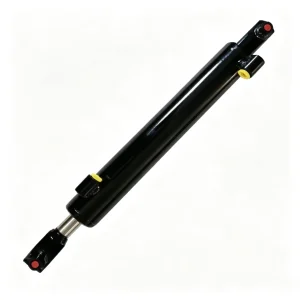
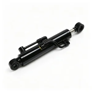
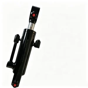
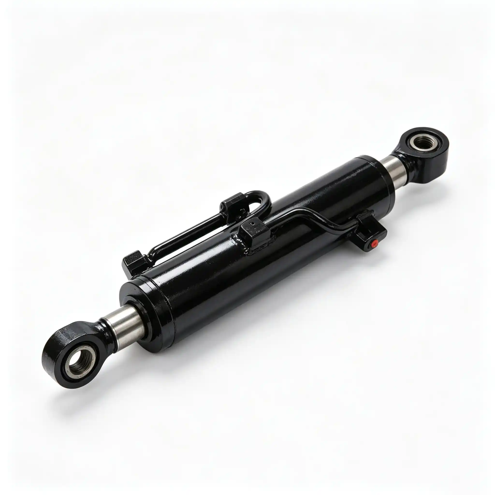
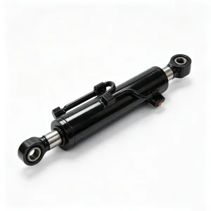
CSYG2074 Boom Cylinder for Mini & Compact Excavators
A 63 mm bore, 35 mm rod, 280 mm stroke boom cylinder engineered for the specific load-bearing, anti-drift, and duty-cycle demands of sub-6-tonne excavators operating in confined urban worksites, pipe-laying trenches, and landscaping environments.
Why Boom Cylinder Failure Costs Mini Excavator Operators More Than Just Downtime
The boom cylinder on a mini excavator is the single component that carries the combined weight of the stick, bucket, and any attached tooling every time the operator lifts. On a 3.5-tonne machine, that suspended load can reach 800–1,100 kg depending on attachment configuration. Unlike the stick or bucket cylinders, the boom cylinder must also hold that load stationary for extended periods — during truck loading pauses, while repositioning, or when the operator steps off the machine. Any internal bypass across the piston seal, or any micro-leak at the rod-seal interface, translates directly into boom drift: the arm slowly descends against operator intent, creating both a safety hazard and a productivity drag.
Compact machines face a compounding challenge. Because they operate in narrow trenches and between structures, the operator cycles the boom continuously at moderate pressures rather than in long, full-stroke sweeps. This generates more rod-seal contact cycles per hour than equivalent full-size machines, accelerating wear on undersized or low-specification cylinders. The CSYG2074 is configured specifically for this duty profile: 63 mm bore for adequate thrust-force headroom within compact system pressures, a hardened 35 mm rod that resists side-load bending in shallow-angle digging, and a 280 mm stroke matched to the geometric envelope of sub-6-tonne boom pivots.
This page documents the engineering rationale behind every key parameter, the metallurgical and sealing technologies that determine service life, and the specific force conditions this cylinder is designed to manage across typical mini excavator worksite patterns.
63 mm Bore / 35 mm Rod / 280 mm Stroke: What Each Dimension Actually Controls
Technical specifications decoded for procurement engineers and site mechanics alike
| Parameter | Value | Engineering Significance |
|---|---|---|
| Bore Diameter | 63 mm | Piston area ≈ 31.2 cm². At 20 MPa system pressure, push force ≈ 62.4 kN — sufficient to lift rated loads with a 15–20% pressure reserve |
| Rod Diameter | 35 mm | Rod area ≈ 9.6 cm². Annulus pull force ≈ 43.2 kN at 20 MPa. Rod slenderness ratio at 280 mm extension remains within Euler buckling safety margins for typical boom-pivot geometry |
| Stroke | 280 mm | Controls the angular range of boom pivot rotation. At typical mini excavator pin-centre dimensions, 280 mm stroke translates to approximately 45–55° boom arc, setting maximum reach and dig depth |
| Installation Distance | 595 mm | Pin-to-pin retracted length. Determines physical fitment in the undercarriage frame pocket. Must be matched within ±1 mm to avoid pre-load stress at hinge pins |
| Application Position | Boom (Main Lift) | Primary static-load bearing cylinder. Anti-drift performance is as critical as dynamic thrust |
| Compatible Machine Class | Mini & Compact, 1–6 t | Suitable for rubber-tracked mini excavators, compact short-radius machines, and farm/utility excavators in this weight class |
Understanding Push Force, Pull Force, and Their Role in Boom Lifting Capacity
A 63 mm bore generates a piston face area of 31.2 cm². Multiplied by a nominal system pressure of 20 MPa, this produces a theoretical push force of 62.4 kN. In practice, line losses, valve pressure drops, and hydraulic fluid viscosity effects reduce effective force to roughly 90–93% of theoretical — approximately 56–58 kN at the pin. That force, acting through the lever arm of the boom pivot geometry, translates to the rated lift capacity displayed on the machine’s load chart.
The 35 mm rod diameter is not arbitrary. A larger rod would increase pull-stroke force on the annulus side, but it would also increase the rod’s cross-sectional mass and the sealing diameter, raising friction and seal contact stress. At 35 mm, the rod achieves a bore-to-rod ratio of approximately 1.8:1 — a ratio that balances adequate pull force for boom-down movements against minimizing seal wear and rod weight within the compact boom geometry.
The 280 mm stroke is the parameter most directly tied to the machine’s operating envelope. Shorter strokes limit maximum boom height and maximum dig depth. Longer strokes in the same bore size would require a thinner rod wall at the head bearing — a structural compromise. At 280 mm, the CSYG2074 preserves adequate head-bearing contact length while delivering the digging arc geometry that machine designers specify for this class.
Induction Hardening, Hard Chrome Plating, and Polyurethane Seal Technology: The Service-Life Triangle
B2B buyers in the replacement cylinder segment are not buying a component — they are buying productive machine-hours before the next seal failure or rod replacement. Every material and process decision on the CSYG2074 is evaluated against that metric.
Piston Rod: 45# Steel Base with High-Frequency Induction Hardening
The piston rod blank is machined from medium-carbon 45# steel (equivalent to SAE 1045), selected for its balance of machinability, tensile strength (≥ 600 MPa), and response to heat treatment. The rod surface is then processed by high-frequency induction hardening, which heats only a controlled skin depth — typically 1.5–3.0 mm — to austenitizing temperature before rapid quenching. The resulting surface hardness reaches HRC 52–58, while the core remains tough and ductile at HRC 28–32. This surface-to-core gradient is essential: a fully hardened rod would be brittle under the bending moments imposed when the excavator’s boom swings against a soil bank or when lifting loads off-centre relative to the boom pivot.
Hard Chrome Plating: Surface Hardness, Oil-Film Retention, and Corrosion Resistance
Following induction hardening, the rod receives a hard chrome plating layer of 25–40 μm applied via hexavalent chromium electroplating. The chrome layer serves three simultaneous functions. First, surface hardness reaches HV 900–1,000 — harder than most abrasive particles encountered in construction dust environments, reducing micro-scratching that otherwise creates leak paths past the rod seal. Second, the chrome surface develops micro-porosity that retains a thin hydraulic-oil film between the rod and the wiper seal, reducing stick-slip friction and preventing dry-contact scoring during initial strokes after cold starts. Third, the chrome provides electrochemical corrosion resistance, critical for machines used in waterlogged trenches, coastal land reclamation, or winter road work where chloride-laden water contacts the rod.
After plating, the rod is precision-ground and polished to a surface roughness of Ra 0.2–0.4 μm. This finish is not aesthetic — it is the parameter that directly determines how long the polyurethane rod seal can maintain its sealing lip geometry before wear causes bypass leakage.
Sealing System: Polyurethane Primary Seals with Nitrile Backup and Dust Wipers
The sealing stack on the CSYG2074 uses a multi-element design across the rod and piston positions. At the rod, the primary dynamic seal is a polyurethane lip seal — the same formulation used in sealing kits from NOK and SKF for this bore range. Polyurethane offers tensile strength roughly three times higher than standard nitrile (NBR), meaning the seal lip maintains its interference contact with the rod surface for longer as the rod surface inevitably micro-roughens over thousands of operating hours. The sealing lip geometry is engineered with a slight positive rake angle — it wipes oil back into the cylinder on the retraction stroke, preventing oil weeping at the rod gland, which is the most visible and earliest sign of seal fatigue in field conditions.
Behind the primary seal sits a secondary backup ring — typically PTFE-filled PTFE or an O-ring in a dovetail groove — that captures any oil that bypasses the primary under momentary pressure spikes. This two-stage system means that a partial degradation of the primary seal does not immediately result in external leakage; the operator retains a maintenance window before fluid loss becomes significant.
The external wiper ring, seated in the rod-gland outer groove, faces the contaminated environment. Made from polyurethane with a dual-lip profile, it scrapes both inward-traveling dirt and outward-traveling oil simultaneously. For mini excavators operating in sandy loam, clay excavation, or compacted gravel, this wiper is the seal system’s first line of defense. Its replacement interval is shorter than the primary seal; designing it as an accessible, separately serviceable element keeps maintenance cost manageable.
- Piston seals: Step-cut PTFE or polyurethane U-cup rings minimize internal bypass across the piston — the direct cause of boom drift. Low friction formulation reduces heat generation in continuous partial-stroke cycling.
- Guide rings: Fiber-reinforced PTFE guide bands at both piston and rod guide positions manage lateral loads without metal-to-metal contact, preserving bore surface integrity over extended service.
- O-ring back-up sets: High-nitrile (≥ 70% ACN content) O-rings at static interfaces resist hydraulic oil degradation and maintain compression set resistance at operating temperatures up to 80°C.
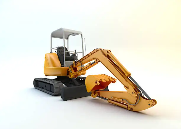
Typical operating environment: confined urban trench work where boom load-holding and anti-drift performance are non-negotiable
Boom Cylinder Force Mechanics: Why Anti-Drift and Static Load-Holding Define This Cylinder’s Specification
The boom cylinder occupies a unique force regime among all excavator cylinders. The stick and bucket cylinders operate primarily in dynamic mode — they are constantly moving during productive work cycles. The boom cylinder, by contrast, spends a significant portion of every working shift holding a static or semi-static load. During truck loading, for example, the boom may hold a fixed height for 15–30 seconds per cycle while the operator swings and dumps. Over a 9-hour shift with 200 loading cycles, that represents 50–100 minutes of pure static load-holding. This is the condition that most rapidly exposes internal piston seal bypass.
The Mechanics of Boom Drift: Internal Bypass vs. External Leakage
Boom drift — the slow, unintended lowering of the boom under gravity — has two possible origins. External leakage at the rod seal causes visible oil weeping and is easy to diagnose. Internal bypass across the piston seal is more insidious: there is no visible oil loss, but hydraulic fluid migrates from the rod-side chamber (high pressure, holding the load) to the piston-side chamber (lower pressure), allowing the cylinder to shorten. A worn piston seal on a boom cylinder can cause 20–50 mm of drift in 5 minutes under full rated load — a safety condition that in many jurisdictions requires the machine to be removed from service immediately.
The CSYG2074’s piston seal package addresses this through seal geometry and material selection. The step-cut piston seal creates a labyrinthine flow path: any oil attempting to bypass must negotiate a non-linear gap profile rather than a simple annular clearance, dramatically increasing the pressure differential required to sustain flow. In quantitative terms, a properly specified step-cut PTFE piston seal in a 63 mm bore cylinder will hold internal bypass below 0.3 cm³/min at 20 MPa — a threshold invisible to machine operation over any normal work period.
Side-Load Management at the Boom Pivot: The Hidden Stress in Mini Excavator Operation
Mini excavators, by virtue of their short wheelbase and rubber-tracked undercarriage, are frequently positioned on cross-slopes during trench work. When the machine is tilted 5–8° laterally — a common urban worksite condition — the boom cylinder experiences a bending moment superimposed on its primary compressive/tensile load. On a 280 mm stroke cylinder with the rod fully extended, even a 3° angular misalignment between pin centres generates a bending moment at the rod-gland bearing. Over extended cycles, this accelerates uneven wear of the rod guide bearing and creates an asymmetric wear pattern on the rod seal lip.
The CSYG2074 addresses this through an elongated rod-guide bearing land — the internal bronze or filled-PTFE bushing that supports the rod at the cylinder head. A longer bearing contact surface distributes side-load over a greater axial length, reducing specific bearing pressure and the resulting rod-tilt at the seal lip. For a 35 mm rod in a 63 mm bore cylinder of this stroke, an adequate guide bearing length is typically 1.2–1.5 times the rod diameter, positioning the seal well within the safe contact-pressure zone.
Push Force (theoretical)
62.4 kN
@ 20 MPa, 63 mm bore
Pull Force (annulus)
43.2 kN
@ 20 MPa, 35 mm rod
Internal Bypass (new seals)
< 0.3 cm³/min
@ rated pressure, static hold
Rod Surface Hardness
HV 900+
Hard chrome over induction-hardened 45# steel
Installation, Cross-Compatibility, and Preventive Maintenance Protocol for Mini Excavator Boom Cylinders
Dimensional Fitment: What to Measure Before Ordering a Replacement
The CSYG2074’s 595 mm installation distance (pin-to-pin, fully retracted) is the primary fitment reference. Before ordering, measure the existing cylinder’s retracted pin-centre distance with the boom in its lowest position. A ±2 mm variance is generally acceptable within the hinge-pin bore tolerance; beyond that, the installation produces pre-load stresses at the clevis pins that accelerate wear of the pin bushings and impose parasitic loads on the cylinder barrel. Bore diameter (63 mm) and stroke (280 mm) must match the original specification; using a cylinder with a different stroke will alter the boom’s maximum height and minimum angle, affecting the machine’s certified load chart ratings.
Hydraulic Port Connection: Thread Standards and Torque Values
Mini excavator boom cylinders in the 1–6 tonne class typically use BSP (British Standard Pipe) or BSPT threaded ports, though some Asian-market machines use metric PF threads. Confirm the thread specification of the existing hoses before installation. Over-torquing port fittings on a steel cylinder barrel with a standard hydraulic line wrench is a common cause of port thread damage that is costly to repair; use a calibrated torque wrench and follow the fitting manufacturer’s torque specification for the specific thread size — typically 50–80 Nm for 3/8″ BSP in this bore class.
Initial Commission and Air-Bleeding Procedure
After installation, air entrapped in the new cylinder will cause erratic boom movement and abnormal noise. Before returning the machine to productive work, cycle the boom slowly through 5–8 full-stroke cycles with the machine stationary and the hydraulic system at idle speed (engine at low throttle). This allows trapped air to migrate into the hydraulic tank via the return line. Do not operate at full hydraulic pressure until smooth, consistent boom movement is confirmed.
Preventive Maintenance Schedule for Extended Seal Life
- Daily (operator check): Inspect the rod surface for visible score marks, pit corrosion, or chrome flaking. Any surface damage that can be felt with a fingernail will abrade the rod seal within weeks. Inspect rod-gland area for oil weeping — a film of oil is acceptable; dripping indicates immediate seal service is required.
- 250-hour interval: Check hydraulic oil contamination level. ISO 4406 cleanliness code of 17/15/12 or better is the minimum for preserving seal life in this bore class. Contaminated oil introduces abrasive particles that act as lapping compound against seal lips and rod surfaces.
- 500-hour interval: Measure boom drift rate by holding a rated load at maximum reach for 5 minutes. Drift exceeding 30 mm indicates internal piston seal bypass approaching service threshold. Reseal at this point avoids barrel scoring from prolonged operation with a deteriorating piston seal.
- Greasing: Apply NLGI #2 EP lithium grease to clevis pins and bushings at the boom pivot per machine OEM schedule — typically every 50–100 hours. Dry pin bushings allow micro-fretting that produces angular misalignment loads directly transmitted to the cylinder rod guide bearing.
- Rod protection in storage: When the machine is out of service for more than two weeks, retract the boom fully to minimize exposed rod length. Apply a light coat of petroleum jelly or rust-preventive oil to any exposed chrome rod surface in humid or coastal environments.
Cross-Brand Compatibility Guidance
The CSYG2074 is designed as a replacement-market cylinder for mini excavators in the 1.5–5 tonne class that share the 63 mm bore / 35 mm rod / 280 mm stroke / 595 mm installation-distance specification. Many machines across Chinese domestic brands, Japanese compact excavators, and European mini digger lines use similar geometric envelopes — exact fitment should always be verified against the machine’s service manual boom cylinder specification table. If your specific machine model is not listed in our compatibility guide, our technical team can review machine drawings or existing cylinder measurements to confirm interchangeability before dispatch.
Request a Quote, Technical Drawing, or Batch Pricing
Our engineering team holds dimensional drawings, seal-kit breakdowns, and cross-reference data for the CSYG2074 and 2,000+ related cylinder part numbers. Whether you are sourcing a single replacement unit, establishing a service-parts inventory for a fleet, or evaluating OEM supply quantities, we can respond within one business day.
एक उद्धरण का अनुरोध करें
Provide your machine model, required quantity, and delivery port. Receive FOB/CIF pricing within 24 hours.
Technical Drawing Request
Full dimensional drawings (PDF/DWG) and seal-kit part list available for qualified buyers and equipment dealers.
Custom Specification
Non-standard bore, rod, stroke, or port configuration? Submit your drawing or existing cylinder measurements for a custom quotation.
- ✓ MOQ: 1 piece for sample orders
- ✓ Standard lead time: 7–15 business days
- ✓ Export packing: wooden crate or fumigated pallet
- ✓ Payment: T/T, LC at sight
- ✓ Quality: 100% pressure-tested before shipment
- ✓ Seal kits supplied separately for field service teams
All CSYG2074 cylinders are pressure-tested to 1.5x rated working pressure before dispatch. Certificates of conformance available on request for fleet and OEM accounts.