
विवरण
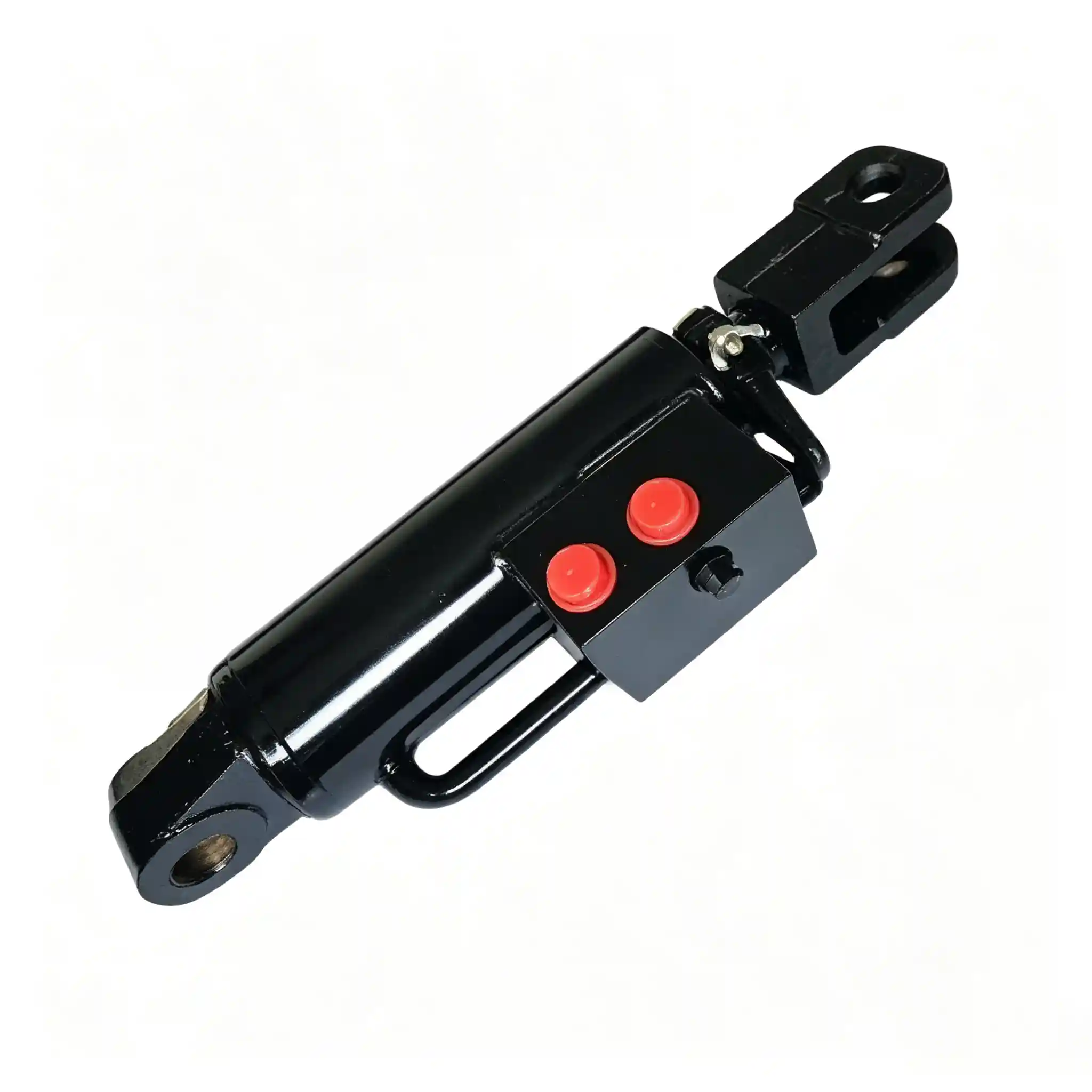
The TB600.55B.2 is a 75 mm bore tractor hydraulic lift cylinder with a 32 mm rod, 110 mm stroke, and 425 mm mounting distance. In three of its four primary dimensions it is identical to the NF75B — the difference is the mounting distance: 425 mm here versus 350 mm on the NF75B. That 75 mm difference is the reason these two cylinders serve different machines and cannot be used as direct replacements for each other.
The 425 mm mounting distance places the TB600.55B.2 in a specific installation class. It is the same mounting distance as the TB600 (80 mm bore, 105 mm stroke) in this product range — which suggests both cylinders may correspond to machines from a related platform family, with bore selection reflecting different force requirements for different models within that family.
Ever-Power supplies the TB600.55B.2 as an aftermarket replacement for agricultural tractor hydraulic lift applications. When ordering, confirm the mounting distance of the existing cylinder — measuring bore and stroke alone is not sufficient to distinguish this model from the NF75B.
TB600.55B.2 — Technical Specifications
| Parameter | Value | Notes |
|---|---|---|
| Bore Diameter | 75 mm | Same as NF75B; ~42% more piston area than 63 mm bore |
| Rod Diameter | 32 mm | Same as NF75B; rod-to-bore ratio 0.43 |
| Stroke | 110 mm | Same as NF75B; total linear travel of piston rod |
| Mounting Distance | 425 mm | 75 mm longer than NF75B (350 mm) — the single distinguishing dimension |
| आवेदन | Agricultural tractor hydraulic lift systems | Confirm 425 mm mounting distance on existing cylinder before ordering |
| Supplier | Ever-Power | OEM and aftermarket supply; custom specifications on inquiry |
425 mm Mounting Distance: What It Means for the Machine This Cylinder Fits
Mounting distance — pin-center to pin-center with the cylinder fully retracted — is the dimension that ties a cylinder to its specific machine installation. The TB600.55B.2’s 425 mm mounting distance means the machine’s two pivot brackets are 425 mm apart when the lift is in the fully lowered position. At full extension, the distance between the same two pin centers is 425 + 110 = 535 mm.
A machine built around this geometry cannot accept a cylinder with a shorter mounting distance — the rod-end pin will not reach its bracket in the retracted position. Equally, a cylinder with a longer mounting distance will push the linkage past its intended lower position before the cylinder is even retracted. Neither error is trivially fixable in the field.
| Model | Bore | Rod | Stroke | Mtg. Dist. | Extended |
|---|---|---|---|---|---|
| NF75B | 75 mm | 32 mm | 110 mm | 350 mm | 460 mm |
| TB600.55B.2 | 75 mm | 32 mm | 110 mm | 425 mm | 535 mm |
The 75 mm gap — seen from the TB600.55B.2 side:
If an NF75B (350 mm mounting distance) is fitted into a machine designed for the TB600.55B.2 (425 mm), the result in the retracted position is that the rod-end pin is 75 mm past its bracket — the cylinder is 75 mm too short to reach its mounting point. The machine’s implement will rest 75 mm closer to the ground than its designed lowest position, and at full extension, the cylinder will have already reached its internal end stop 75 mm before the lift arm reaches its intended maximum height. The lift arm travel range shifts entirely relative to the linkage design. Neither condition is acceptable for normal machine operation.
425 mm Mounting Distance Across the Product Range
Within this product range, two cylinders share a 425 mm mounting distance: the TB600.55B.2 (75 mm bore, 32 mm rod, 110 mm stroke) and the TB600 (80 mm bore, 35 mm rod, 105 mm stroke). Despite the shared mounting geometry, they are not interchangeable — bore, rod, and stroke all differ. The shared mounting distance is a geometric constraint of the machine’s bracket design; the different bores indicate different force requirements for different models or configurations within the machine family.
| Model | Bore | Rod | Stroke | Mtg. Dist. | Force @ 160 bar (ref.) |
|---|---|---|---|---|---|
| TB600.55B.2 | 75 mm | 32 mm | 110 mm | 425 mm | ~70.7 kN (theoretical) |
| TB600 | 80 mm | 35 mm | 105 mm | 425 mm | ~80.4 kN (theoretical) |
The 13% difference in theoretical force between these two cylinders at the same reference pressure corresponds to the difference between a 75 mm and an 80 mm bore. A machine designed for the TB600.55B.2’s 75 mm bore has its hydraulic system pressure, pump capacity, and linkage structural load all calibrated to that force level. Fitting the TB600 (80 mm bore) into the same bracket position would increase force output — and flow demand — beyond what the system was designed for, which is not a straightforward upgrade.
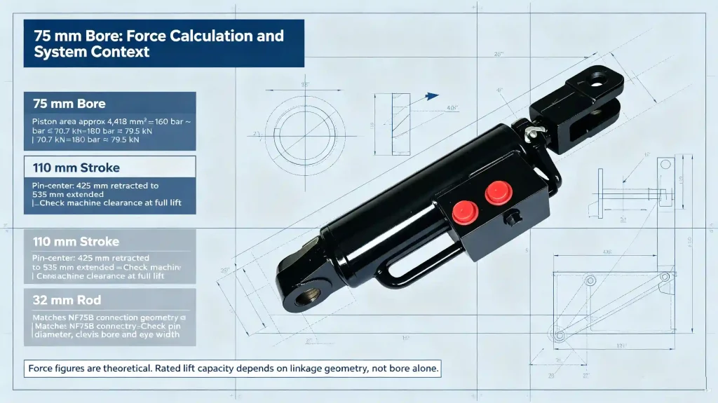
75 mm Bore: Force Calculation and System Context
At 75 mm bore, piston area is approximately 4,418 mm² (π × 37.5²). This is the same calculation as for the NF75B — both cylinders share the 75 mm bore. At a reference pressure of 160 bar, theoretical extension force is approximately 70.7 kN. At 180 bar, approximately 79.5 kN.
These figures represent the force at the rod tip along the cylinder axis. They are not the tractor’s rated hitch lifting capacity. That capacity depends on how the linkage converts cylinder force into lifting moment at the hitch points — a function of lift arm length, cylinder attachment position, and the angular geometry of the mechanism at different positions in the lift range. Tractor manufacturers establish rated lift capacity through standardized whole-machine testing, not from cylinder bore calculations.
Engineering Reference Note: Force figures are theoretical calculations based on bore geometry and reference pressure only — not rated product specifications for the TB600.55B.2. Actual output depends on the system’s operating pressure, valve restrictions, and circuit efficiency. No rated pressure for the TB600.55B.2 has been confirmed by Ever-Power for publication here.
110 mm Stroke Within the 425 mm Installation Frame
The TB600.55B.2 operates between 425 mm (fully retracted) and 535 mm (fully extended) pin-center to pin-center. That 535 mm extended length is the critical clearance dimension on the machine side: the lift arm and its associated linkage must be able to accommodate 535 mm of pin-center distance at full lift without mechanical interference.
At 110 mm stroke, the cylinder provides the same implement travel range as the NF75B at the same 75 mm bore — the travel range and force potential are identical. What is different is where that range sits relative to the machine’s structure. The TB600.55B.2 starts its travel 75 mm further from the base-end pivot than the NF75B does. That geometrical offset affects the effective moment arm at every point in the lift range, which is part of why different machines in the same horsepower class can specify different mounting distances even for cylinders with the same bore and stroke.
This also explains why the mounting distance is a machine-specific dimension rather than a cylinder-selection preference. It is determined by the structural design of the machine — the positions of the pivot brackets and the lift arm geometry — not by the buyer’s preference for a longer or shorter cylinder.
32 mm Rod: Fitment and Connection Considerations
The 32 mm rod on the TB600.55B.2 matches the NF75B exactly. In terms of bending stiffness and buckling resistance, a 32 mm rod at 110 mm stroke is entirely adequate for a tractor lift cylinder operating in normal agricultural conditions. At full extension, the unsupported rod length is short — buckling under axial compressive load is not a concern at these dimensions.
For replacement purposes, the rod diameter determines the rod-end connection geometry. The pin diameter, clevis bore, and eye width at the rod end are all sized for a 32 mm rod. If a previous repair fitted a cylinder with a different rod diameter, these connection dimensions may have been modified — in that case, the replacement should restore the original 32 mm rod specification and the original connection dimensions, rather than perpetuating an adaptation that may have introduced misalignment or stress concentrations in the pin joint.
Side loading — lateral force on the rod from misalignment in the cylinder mounting — is the most common cause of premature rod seal wear in agricultural lift cylinders. It has nothing to do with rod diameter selection; it is an installation geometry issue. If the previous cylinder showed uneven seal wear or a bent rod without obvious impact damage, check the alignment of the cylinder axis with the direction of lift arm travel before fitting the replacement.
Confirming TB600.55B.2 Is the Correct Replacement
Because the TB600.55B.2 and NF75B share bore, rod, and stroke, the mounting distance measurement is what separates them. Measure all four primary dimensions before ordering.
| Measurement | TB600.55B.2 Value | How to Measure |
|---|---|---|
| Mounting Distance ← decisive | 425 mm | Pin-center to pin-center, cylinder fully retracted; tape measure |
| Bore | 75 mm | Inside barrel diameter; or OD minus wall thickness × 2 |
| Rod Diameter | 32 mm | Calipers on clean, undamaged section of rod |
| Stroke | 110 mm | Extended pin-pin (535 mm) minus retracted (425 mm) |
| Rod-end pin diameter | To be measured | Calipers; note if original pin is still in place |
| Base-end pin diameter | To be measured | Measure separately; may differ from rod end |
| End connection type | To be confirmed | Identify clevis, eye, or other at both ends |
| Port specification | To be confirmed | Thread type, size, number of ports, location on body |
When the existing cylinder cannot be fully measured: The mounting distance (425 mm) can typically be measured from the installed cylinder without removing it, using a tape measure between pin centers. This single measurement, combined with bore and rod diameter, is usually sufficient to confirm TB600.55B.2 versus NF75B. If the cylinder is already removed and damaged, include photographs of both mounting ends — the end connection style and any body markings help confirm the correct model before quotation.
Diagnosing Hydraulic Lift Faults on Machines Using the TB600.55B.2
Most hydraulic lift faults are circuit-level problems rather than cylinder failures. The TB600.55B.2, like any hydraulic lift cylinder, should not be replaced without first confirming that the cylinder is actually the fault source. The two most common errors are replacing the cylinder when the control valve is the real source of drift, and replacing the cylinder when low system pressure or a worn pump is the real source of weak lift.
Implement drifts down slowly in neutral
Isolate the cylinder by capping its ports with hoses disconnected. Raise the implement, hold the lift control in neutral, then release it. If drift stops with ports capped, the cylinder is holding pressure — the leakage is in the circuit, not the cylinder. The control valve is the most common source in this situation. Only if drift persists with ports capped is the cylinder’s piston seal the likely source.
Lift force feels weaker than before
Measure system hydraulic pressure with a gauge at the circuit test point — if available — before attributing weak lift to the cylinder. A pump that has lost output pressure will reduce lift force across the entire hydraulic system. The relief valve setting may have also shifted over time. Cylinder internal bypass typically manifests as load drift, not as a sudden or gradual reduction in maximum force.
External oil leak at the rod seal
Before ordering seals, clean the rod and inspect its surface under good light. Longitudinal scratches — the kind left by field debris that passed the wiper seal — will destroy new seals in the same way they destroyed the old ones. A wiper seal replacement alongside the rod seal, and a check of rod surface condition, addresses both the symptom and its likely cause. A bent rod is not fixable by seal replacement and requires cylinder body work or replacement.
Implement travel range shifted after previous cylinder replacement
If a previous repair fitted an NF75B (350 mm mounting distance) in place of the TB600.55B.2 (425 mm), the entire lift range will have shifted. The implement will sit lower than designed at full retraction, and the cylinder will reach its internal stop before the lift arm reaches its intended maximum height. Check the mounting distance of the currently installed cylinder before ordering a replacement — if it reads 350 mm where 425 mm is required, the cylinder specification is incorrect.
Requesting a Quotation for TB600.55B.2
The 425 mm mounting distance is the single most important figure to confirm and include in any inquiry — it is what distinguishes this model from the NF75B in a product family where bore and stroke are identical between the two.
- Reference number: TB600.55B.2
- Confirmed mounting distance: 425 mm — the key identifier versus NF75B
- Confirmed bore (75 mm), rod diameter (32 mm), stroke (110 mm)
- Pin diameters at rod end and base end (measure separately)
- End connection type at both ends
- Port thread type, size, count, and location
- Single-acting or double-acting (confirm from port count)
- Order quantity
- Machine model and year, if known
- Working pressure, if known from machine documentation
- Photos of existing cylinder: full side view, both mounting ends, port detail, any visible markings
Frequently Asked Questions — TB600.55B.2
What is the difference between the TB600.55B.2 and the NF75B?
One dimension: mounting distance. The TB600.55B.2 has a 425 mm mounting distance; the NF75B has 350 mm. Bore (75 mm), rod (32 mm), and stroke (110 mm) are identical between the two. Those 75 mm of additional mounting distance mean the TB600.55B.2 is designed for a machine with bracket pivot points 75 mm further apart than the machine the NF75B serves. Fitting one in place of the other shifts the entire lift travel range relative to the linkage geometry — the implement will not sit at the correct lowered position, and full lift height will not be achieved.
How do I measure mounting distance on an installed cylinder?
With the implement fully lowered and the cylinder fully retracted, measure from the center of the base-end pin to the center of the rod-end pin using a tape measure. For the TB600.55B.2, this should read 425 mm. The measurement can usually be taken with the cylinder installed on the machine — you do not need to remove it. Take the measurement when the lift control is confirmed in the fully lowered position, as any partial extension will add to the reading.
Can the TB600.55B.2 replace the TB600 (80 mm bore), which shares the same 425 mm mounting distance?
No. While both cylinders share the 425 mm mounting distance, they differ in bore (75 mm vs 80 mm), rod (32 mm vs 35 mm), and stroke (110 mm vs 105 mm). The bore difference means the two generate different force outputs at the same pressure — approximately 70.7 kN versus 80.4 kN at 160 bar reference. The rod diameter difference means the end connection geometry differs. The stroke difference means the lift travel range differs by 5 mm. All three differences prevent a direct substitution.
My implement sits lower than it should after a previous cylinder replacement. What should I check?
Measure the mounting distance of the currently installed cylinder. If it reads 350 mm rather than the correct 425 mm, an NF75B was fitted instead of a TB600.55B.2 at some point. The shorter mounting distance shifts the cylinder’s retracted position 75 mm closer to the base-end pivot, which moves the implement’s lowered position lower than designed. At full extension, the cylinder hits its internal stop 75 mm before the lift arm reaches its intended height. Replacing the 350 mm cylinder with the correct 425 mm unit restores the designed travel range.
Does the hydraulic cylinder bore determine how much my tractor can lift?
Bore determines the force the cylinder generates at a given hydraulic pressure. What the tractor can actually lift at the hitch is determined by the entire lift system — the cylinder force, the length of the lift arms, the mechanical advantage of the linkage, and the angle at which the cylinder acts on the pivot. The rated lift capacity figure in the tractor’s specification sheet is the output of whole-machine testing to a defined standard. It is not derived from cylinder bore and pressure alone. The cylinder’s force contribution is one input to that system, not the system’s total output.
What information should I include when requesting a quote?
The most critical detail is the confirmed mounting distance of 425 mm — without it, the TB600.55B.2 cannot be distinguished from the NF75B on bore and stroke alone. Also include: bore (75 mm), rod diameter (32 mm), stroke (110 mm), pin diameters at both ends, end connection type at both ends, port thread specification and number of ports, quantity, and machine model and year if known. Photographs of the existing cylinder — both mounting ends, full side view, and port location — help confirm end-connection geometry before quotation.


