
Cosmetic bottle manufacturers choosing between PET and PETG face a decision that goes beyond material cost. The resin choice determines preform geometry, conditioning station temperature profile, allowable stretch ratio, and ultimately which machine platform — multi-cavity ES or single-cavity FS — can actually deliver the dimensional tolerances the container design requires. This guide works through the processing differences of both materials from a machine-configuration standpoint, with direct reference to the parameters that drive rejection rates on a production line.
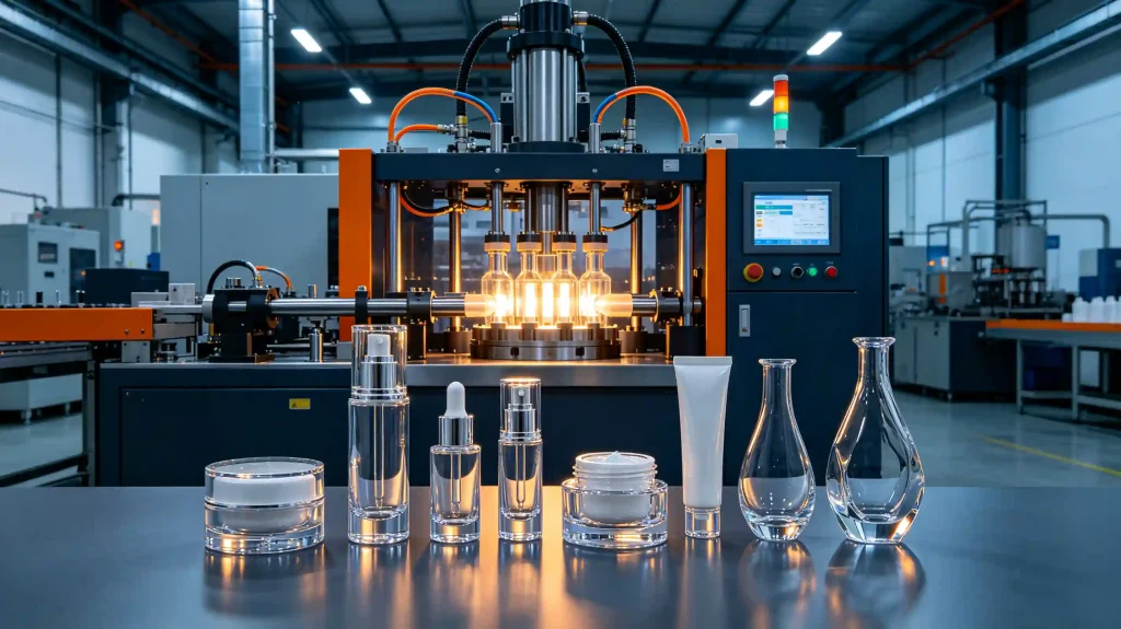
Why PET and PETG Process Differently in an Injection Stretch Blow Molding Machine
Both PET (polyethylene terephthalate) and PETG (polyethylene terephthalate glycol-modified) are amorphous when injection-molded into preforms, and both need to be conditioned above their glass transition temperature (Tg) before biaxial orientation is possible. That is where the similarity ends.
Glass Transition Temperatures & Processing Windows
| Material | Tg (°C) | Optimal Blow Window (°C) | Crystallization Risk |
|---|---|---|---|
| PET (bottle-grade, IV 0.72–0.84 dL/g) | 72–76 °C | 95–115 °C | High above 120 °C |
| PETG (copolymer, IV 0.76–0.80 dL/g) | 78–83 °C | 80–95 °C | None — amorphous |
PETG’s higher Tg means the conditioning station must bring the preform to a higher absolute temperature before the material becomes sufficiently compliant for stretching. But its complete absence of crystallization means there is no upper temperature boundary where the material becomes hazy or loses orientation memory. On a PET preform, pushing conditioning temperature above approximately 120–125 °C triggers strain-induced crystallization in the shoulder zone before the stretch rod contacts the preform — producing whitish opacity that cannot be recovered in the blow cycle.
Practical consequence: PETG conditioning is more forgiving in the upper temperature range but demands precise floor management. PET conditioning demands precise ceiling management. Confusing the two is the most common machine setup error on a cosmetic bottle line switching materials.
Stretch Ratio Constraints: PET vs PETG in Cosmetic Bottle Geometries
Injection stretch blow molding achieves its mechanical and optical properties through biaxial orientation — the simultaneous axial stretch (from the stretch rod) and hoop stretch (from blow pressure). The ratio of final container dimensions to preform dimensions defines the stretch ratio.
Axial Stretch Ratio (SRa) Final container height ÷ preform body length | Hoop Stretch Ratio (SRh) Final container body diameter ÷ preform body diameter | Planar Stretch Ratio SRa × SRh — the combined biaxial orientation index |
For standard PET cosmetic bottles, the recommended planar stretch ratio is 8–12. Below 8, the material does not achieve sufficient biaxial orientation for the optical clarity and top-load resistance the container needs. Above 14–16, micro-crazing can occur at stress concentration points — typically at the heel radius and the shoulder transition.
PETG tolerates a narrower planar stretch ratio: typically 6–10. Because PETG does not crystallize under strain, it cannot develop the strain-hardening behavior that PET relies on to resist over-stretch at high ratios. Designing a PETG cosmetic bottle with a planar stretch ratio above 10 produces uncontrolled wall thinning in the panel zones, which shows as visible soft spots under shelf lighting.
Machine implication: A serum bottle with a 30mm body diameter and 180mm body height has an axial stretch ratio of approximately 5.5–6.0. Achieving this on PETG requires extended conditioning dwell time — adjustable from 5 to 20 seconds on the HGA series — to ensure the material is compliant enough to accept full rod travel without tearing.
Surface Finish Requirements and How Each Material Responds
In cosmetic packaging, the container surface is part of the product presentation. The relevant defect categories differ between PET and PETG, and diagnosing them incorrectly leads to machine adjustments that solve nothing.
PET Defect Profile ⚠ Weld Line Visibility Gate marks on PET preforms are unavoidable. On transparent cosmetic bottles, even low-stress weld lines below the fill waterline constitute visual rejects. Gate position is the control — mold design stage, not machine setting. ⚠ Birefringent Banding Stress-induced optical banding in PET panels is caused by circumferentially non-uniform conditioning. Controlled via the 10-zone independent IR lamp output map on the HGA ES-platform conditioning station. ✖ Crystalline Haze (Stress Whitening) Triggered above ~120 °C in the shoulder zone. Appears as permanent opaque white haze. Prevention: set shoulder-zone lamp output 8–12% below body zone. Irrecoverable once formed — must be caught in setup, not QC. | PETG Defect Profile ⚠ Weld Line Stress Cracking PETG has lower stress crack resistance than oriented PET. A weld line in a stress concentration zone (panel corner, shoulder transition) is a potential structural failure point, not merely a cosmetic defect. Gate location must account for weld line position. ⚠ Scratch Sensitivity PETG surface hardness (pencil hardness B–HB) is lower than oriented PET (H–2H post-orientation). Transport handling and label application lines require softer contact surfaces for PETG cosmetic containers. ⚠ Gate Area Haze PETG does not benefit from strain-induced crystallization to improve gate clarity. Haze at the gate zone originates in the injection molding conditions — a preform supplier quality issue, not a blow machine parameter. Verify in incoming preform inspection. |
Machine Platform Selection: ES Multi-Cavity vs FS Single-Cavity
The choice between the ES and FS platforms is driven by two primary factors: container geometry and required output. Below is the decision logic for each.
ES Platform (2–6 Cavity) — PET & Standard PETG
The ES platform covers 2-cavity through 6-cavity configurations. The HGA.ES-2C114.3 handles PET cosmetic containers up to 1,000 ml; the HGA.ES-6C114 reaches 5,400 bph on containers up to 1,500 ml.
| ✓Container cross-section is circular or mildly oval (aspect ratio ≤ 1.6:1) |
| ✓Neck finish is standard (28mm PCO, 38mm, 48mm, or other commercial sizes) |
| ✓Material is PET or PETG in standard preform geometries |
| ✓Output requirement exceeds 1,500 bph — requiring 3 or more cavities |
| ✓Container height is within the clamping envelope (up to 330mm on ES-4C114.3) |
FS Platform (Single-Cavity) — PETG Irregular Geometries
| ▶Container cross-section is non-circular: oval with aspect ratio > 1.6:1, multi-faceted, or asymmetric |
| ▶Container has an angled or offset neck relative to the container centroid |
| ▶Material is PETG in a high-clarity premium application with irregular geometry |
| ▶Output requirement is below 700 bph |
| ▶Container body diameter exceeds 190mm (FS-1CG220 and FS-2CG220 only) |
Platform Comparison — HGA Cosmetic Machine Range
| Platform | Max Cavities | Max Output (bph) | Geometry Support | Recommended Resin |
|---|---|---|---|---|
| HGA.ES series | 6 | 7,200 | Mild oval, standard round | PET, PETG (standard preforms) |
| HGA.FS series | 2 | 1,000 | High-difficulty irregular | PETG, PC, PCTG |
Output penalty of choosing FS: A single-cavity FS-1CG150 runs at 700 bph on a 2,500 ml PETG container. The equivalent ES-2C150 reaches 1,800 bph on the same volume. Choosing the FS platform means accepting a 2.5× output penalty — a production planning constraint that must be calculated before committing to a container design with high geometric complexity.
Energy Consumption: PET vs PETG Conditioning Load
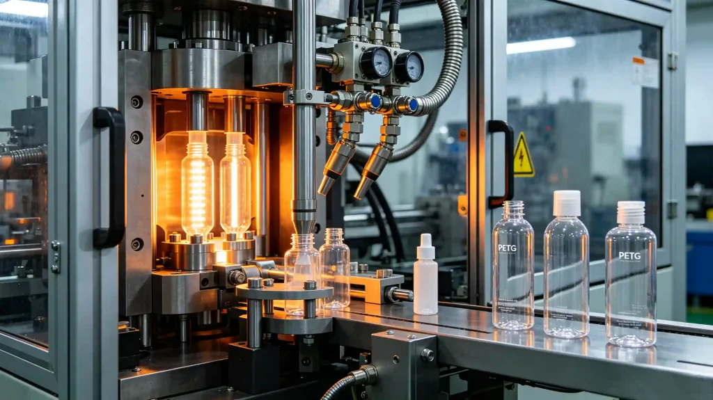
Because PETG requires a higher conditioning temperature floor, the heating power demand per cycle is marginally higher for PETG production than for equivalent PET production on the same model. On an HGA.ES-2C114.3 machine (max heating power 50 kW, typical operating consumption 16 kW), the difference is approximately 10–15% higher heating element duty cycle for PETG compared to a standard PET cosmetic bottle preform — not enough to change the compressor or power supply specification, but enough to appear in the electricity cost calculation over a production year.
Servo drive systems reduce cycle-to-cycle energy variation regardless of resin type. The HGA series servo motor drives cut total machine energy consumption by 30–40% versus hydraulic-drive equivalents. This saving applies equally to PET and PETG production runs.
Material Switching Between PET and PETG: What Changes on the Machine
If a production line runs both PET and PETG cosmetic bottles on the same machine — a common configuration for personal care contract manufacturers — the changeover procedure involves three adjustments. No mechanical retrofit is required. The mold set remains the same.
| ||
| ||
|
Key Decision Summary
| Decision Factor | Choose PET | Choose PETG |
|---|---|---|
| Container geometry | Round, mild oval | Irregular, asymmetric, multi-faceted |
| Required clarity | High (oriented) | Very high (amorphous throughout) |
| Scratch resistance | Better (H–2H hardness) | Lower (B–HB hardness) |
| Crystallization risk | Present — ceiling temp control required | None — amorphous at all temperatures |
| Machine platform | ES multi-cavity preferred | FS single-cavity for complex shapes |
| Planar stretch ratio | 8–12 (optimal) | 6–10 (do not exceed 11) |
| Output vs equivalent cavity | Higher (shorter cooling dwell) | ~5–8% lower (longer cooling dwell) |
| Preform availability | Wide — standard PCO sizes | More limited — confirm supply first |
Pertanyaan yang Sering Diajukan
▶ Can PET and PETG be processed on the same mold set?
▶ Why does PETG produce better clarity in irregular shapes than PET?
▶ What is the maximum wall thickness the FS platform can condition correctly for PETG?
▶ Does processing PETG void the food-contact compliance of the container?
Ready to specify your cosmetic bottle line?
Share your container volume, body diameter, neck finish, and target BPH — receive a specific model recommendation from the 23-model HGA range within 24 hours.