Deskripsi
Hydraulic Cylinders › Dozer Blade Cylinders › Mini & Compact Excavators
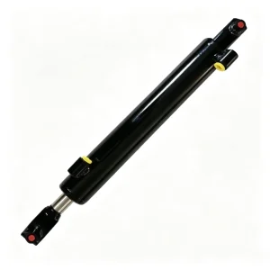
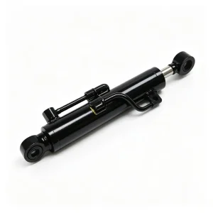
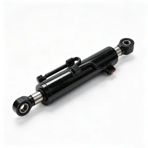
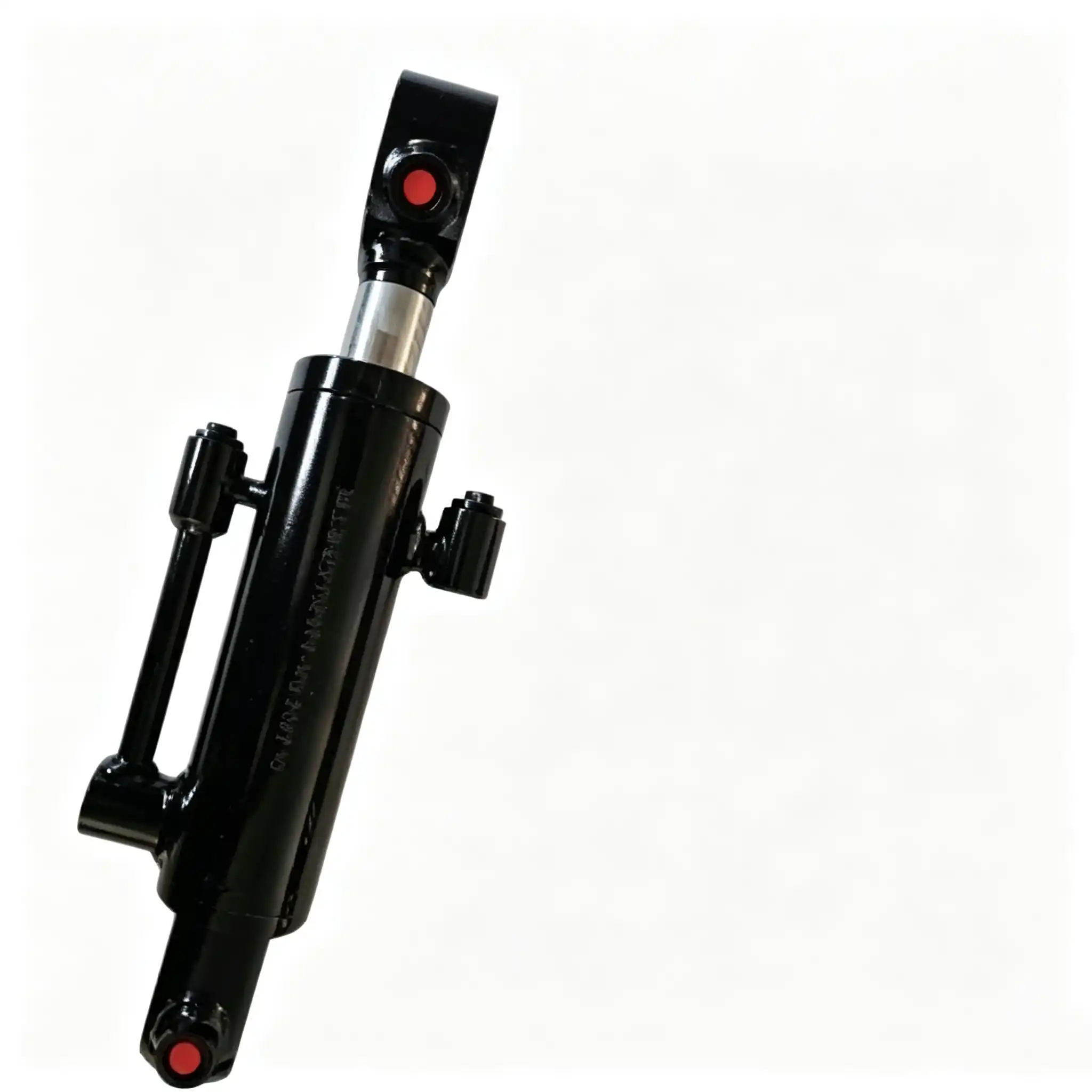
CSYG2077 Dozer Blade Cylinder for Mini & Compact Excavators
A 50 mm bore, 30 mm rod, 270 mm stroke dozer blade cylinder built for the lowest and most punishment-exposed position on a mini excavator — where direct ground-strike loading, crushed stone impact, and sustained grading cycles define the mechanical environment, not the hydraulic circuit alone.
The Dozer Blade Cylinder on a Mini Excavator: The Most Mechanically Abused Component That Operators Forget to Inspect
Among all five hydraulic cylinders on a compact excavator, the dozer blade cylinder occupies the position with the least visibility to the operator and the most severe mechanical environment in absolute terms. It sits between the undercarriage frame and the blade — typically 150–300 mm above ground level — which places it in the direct path of material ejected backward from the blade cutting edge: crushed stone, compressed soil clods, broken concrete fragments, and in demolition environments, rebar sections and masonry rubble. While the boom, stick, and bucket cylinders operate in open air above the digging zone, the dozer cylinder operates at grade level, in the debris field created by the machine’s own work.
The loading pattern on this cylinder is also structurally distinct from all other positions. The boom cylinder carries predictable vertical loads governed by the suspended weight of the attachment. The stick and bucket cylinders experience well-defined push and pull forces through their linkage geometry. The dozer blade cylinder, in contrast, experiences unpredictable shock loads every time the blade contacts an embedded rock, a subsurface concrete edge, or a compacted gravel layer during a grading pass. These are not sinusoidal hydraulic pressure cycles — they are sharp, high-amplitude impulses transmitted directly through the blade, the blade frame, and into the cylinder’s mounting pins and barrel body. A cylinder specified only for its bore force output, without consideration for impact resistance in the barrel, rod, and end-cap weld geometry, will develop fatigue cracks at the barrel-to-end-cap interface long before its seals reach service life.
The CSYG2077 is configured with this mechanical reality as the primary design constraint. Its 50 mm bore delivers the grading force required to hold blade height and push material across compacted ground. Its 30 mm rod is dimensioned for the bending moments imposed when the blade contacts asymmetric ground resistance. The 270 mm stroke defines the full blade height range from maximum float to maximum raised position. And its construction standard — barrel wall thickness, end-cap weld geometry, and rod-end clevis robustness — is specified for impact loading, not just steady hydraulic pressure.
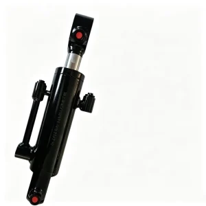
50 mm Bore / 30 mm Rod / 270 mm Stroke: What Each Dimension Determines in Blade Grading Performance
Technical parameters interpreted for plant managers, equipment distributors, and site mechanics
| Parameter | Value | Engineering Significance |
|---|---|---|
| Bore Diameter | 50 mm | Piston area ≈ 19.6 cm². Push force ≈ 39.3 kN at 20 MPa — sufficient to hold blade float against ground reaction forces and maintain grade during sustained pushing passes on compacted aggregate |
| Rod Diameter | 30 mm | Annulus pull force ≈ 25.1 kN at 20 MPa for blade raise. Rod section modulus adequate for bending moments from asymmetric blade loading when one blade end contacts a buried object. Induction-hardened surface resists stone-chip impact scoring at this exposed position |
| Stroke | 270 mm | Sets the total blade height travel from maximum float (blade below ground level for grading) to fully raised (blade clear of ground for tracked travel). At 270 mm, this covers the blade pivot geometry of compact excavators in the 1.5–5 tonne class without requiring the cylinder to work at extreme extension angles that increase rod side-loading |
| Installation Distance | 520 mm | Pin-to-pin retracted length between undercarriage frame pivot and blade-arm pivot. Critical to verify before ordering — a mismatched installation distance prevents the blade from reaching the full float position needed for grade work |
| Application Position | Dozer Blade (Lift/Float) | Lowest cylinder on the machine. Highest impact loading from ground contact. Highest exposure to debris, water, and chemical contamination from road surfaces and earthworks |
| Machine Class | Mini & Compact, 1.5–5 t | Matched to the undercarriage frame geometry and blade pivot dimensions of rubber-tracked mini excavators with factory-fitted dozer blades in this weight class |
How 270 mm Stroke Controls Blade Float Range and Grade Holding Precision
The dozer blade cylinder’s stroke governs both the blade’s maximum working depth (float position, cylinder retracted) and its maximum clear height for machine travel (cylinder extended). On a 2–3 tonne mini excavator with a typical blade pivot-arm length of 300–380 mm, a 270 mm cylinder stroke translates to approximately 180–220 mm of vertical blade travel at the blade cutting edge. This is the practical range within which the operator grades, back-fills trench spoil, and levels surface material.
Precision in grade holding during a sustained pass depends not on stroke length but on the hydraulic system’s ability to hold the cylinder at a fixed extension against the variable ground reaction forces pushing up on the blade. This is where piston seal quality becomes directly relevant to grading accuracy — any internal bypass that allows the cylinder to slowly retract under blade loading will cause the blade to dig progressively deeper as the pass continues, producing an uneven surface that requires a corrective pass. The CSYG2077’s piston seal specification is chosen for static hold accuracy at mid-stroke, not just dynamic cycling endurance.
Impact-Rated Construction and Ground-Level Sealing: Material Choices That Distinguish a Field-Proven Dozer Cylinder from a Catalogue Part
Barrel Wall and End-Cap Weld: Where Shock Fatigue Initiates on Underspecified Cylinders
The structural weak point on dozer blade cylinders subjected to frequent ground-strike loading is not the piston seal or the rod — it is the barrel-to-end-cap interface. On cylinders with inadequate barrel wall thickness or with end-cap welds that are not stress-relieved after welding, residual tensile stresses in the heat-affected zone combine with cyclic impact loading to initiate fatigue cracks that propagate through the weld over 300–600 operating hours. These cracks do not produce immediate catastrophic failure — they begin as hairline fractures that leak only under pressure, typically appearing as a wet stain in the weld bead rather than an active stream of oil. By the time visible leakage is noticed, the crack has usually propagated far enough that the cylinder barrel is non-repairable.
The CSYG2077 barrel is produced from cold-drawn seamless steel tube — the same base material standard used in OEM excavator cylinder production — which provides a uniform, inclusion-free microstructure across the barrel wall. End-cap attachment uses full-penetration welding with post-weld stress relief heat treatment, reducing the residual tensile stress level in the heat-affected zone from the 200–350 MPa range typical of as-welded construction down to 50–100 MPa. At this residual stress level, the effective fatigue life of the weld joint under the impact loading profile of dozer blade service is extended by a factor of 3–5 compared to non-stress-relieved construction.
Piston Rod: Induction Hardening and Hard Chrome for an Environment That Attacks Both Properties
The 30 mm rod is induction-hardened to HRC 54–58 at the surface over a 1.5–2.5 mm case depth, with the 45# steel core remaining at HRC 28–32. The ground-level position of the dozer cylinder means the rod is exposed to stone chip impact from two directions: material ejected backward from the blade during grading passes, and gravel or debris thrown up by the rubber tracks during machine travel. A fully through-hardened rod would chip rather than dent under these impacts — the hard case / ductile core structure allows the impact energy to be absorbed by localised plastic deformation of the core material rather than propagating as a brittle fracture from the surface inward.
The hard chrome plating layer of 25–40 μm achieves HV 900–1,000 and provides three functional properties simultaneously relevant to this position. First, scratch resistance against the fine abrasive particles carried in the blade backwash — particles too fine to cause visible impact marks but capable of micro-scoring a bare steel or lightly plated surface over time. Second, corrosion resistance against standing water, road salt, and chemical residues from earthworks on contaminated sites. Third, the oil-retentive micro-porosity that maintains a boundary lubricant film at the wiper seal interface between operating cycles — reducing dry-contact scoring on the first stroke after the machine has been left overnight in cold or freezing conditions.
Heavy-Duty Wiper Seal: First Defence Against Grade-Level Contamination
The wiper seal on the CSYG2077 uses a heavier-section polyurethane formulation than the equivalent seal on the boom or stick cylinder — a specification difference driven by the volume and particle size of contaminants encountered at blade height. During a grading pass, the rod extends and retracts through a zone that may contain freshly crushed aggregate particles of 3–8 mm diameter, pressed mud, and tarmac fines. A standard single-lip wiper of the type adequate for the boom or stick cylinder position cannot reliably exclude particles in this size range at the contact pressure levels generated by a lightly pre-loaded wiper lip.
The CSYG2077 uses a dual-lip wiper with increased lip interference — the contact force between the wiper lip and the rod surface is higher than on lighter-duty positions, maintaining positive exclusion against larger particles at the cost of marginally higher friction on the retraction stroke. This friction penalty is immaterial for the dozer cylinder’s low-speed, position-holding operating pattern; it would be a meaningful efficiency loss on the stick cylinder’s high-frequency dynamic cycling, but the dozer does not share that duty cycle.
- Primary rod seal: Polyurethane U-cup with self-energising lip geometry. Pressure in the cylinder bore increases lip contact force against the rod surface during grading loads, maintaining bypass-free grade holding at mid-stroke positions.
- Piston seal: Step-cut PTFE or polyurethane U-cup configuration. Controls internal bypass that would cause the blade to drift downward under its own weight during travel — a hazard on road surfaces where an unexpected blade float-down can contact the asphalt at machine travel speed.
- End-cap O-ring static seals: High-ACN nitrile (≥ 70% acrylonitrile) for resistance to mineral hydraulic oil degradation and compression set at the elevated temperatures generated during sustained grading cycles.
- Guide rings: Fibre-reinforced PTFE guide bands prevent metal-to-barrel contact under the lateral loads imposed when the blade strikes an asymmetric obstacle — protecting barrel bore surface finish from the scoring that would otherwise initiate accelerated piston seal bypass.
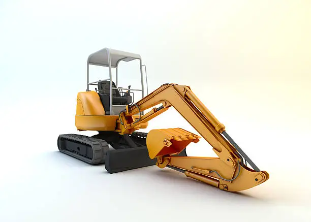
Grade-level operation: the dozer blade cylinder works within the machine’s debris field, subject to stone-chip impact, pressurised mud, and road surface contamination on every pass
Ground-Strike Impulse Loading, Asymmetric Blade Contact, and Grade-Holding Precision: The Three Mechanical Demands That Govern Dozer Cylinder Specification
Ground-Strike Impulse: The Load Type That Specification Sheets Do Not Capture
When a dozer blade contacts an embedded stone or a subsurface concrete edge during a grading pass, the impact energy is transmitted to the cylinder as a pressure spike that can reach 2.5–4× the nominal system pressure within 5–20 milliseconds — well within the response time of the machine’s hydraulic relief valve, which typically requires 30–80 milliseconds to open fully. This means the cylinder barrel, end-cap welds, mounting pins, and rod-end clevis must absorb the peak of each impact load internally before the pressure relief circuit can respond. Over a shift of sustained grading in rocky or rubble-contaminated ground, a mini excavator dozer blade cylinder may experience 50–200 of these sub-100 ms pressure spikes per hour.
The cumulative fatigue damage from these events is not proportional to their number — it is governed by the amplitude of each spike relative to the material’s fatigue endurance limit. At stress amplitudes below the endurance limit of the barrel steel, fatigue crack initiation does not occur regardless of cycle count. The design objective is therefore to keep the peak stress at all structural stress-concentration points (weld toes, port boss edges, rod-end thread roots) below the endurance limit of the material during the worst-credible ground-strike event. This is a structural engineering calculation that does not appear in a hydraulic cylinder’s pressure rating — it requires knowledge of the barrel geometry, wall thickness, material fatigue properties, and the stress-concentration factors at each feature.
Asymmetric Blade Loading: When One End of the Blade Contacts Before the Other
Mini excavator blades are typically 800–1,400 mm wide, supported by a central pivot arm connected to the single dozer cylinder. When the blade contacts a buried object on one side only — the left corner strikes a concrete block while the right corner is over soft soil — the blade experiences a twisting moment around its vertical axis. This twisting is transmitted through the blade pivot arm to the cylinder rod as a lateral force component perpendicular to the rod’s centreline. At 270 mm full extension, the rod functions as a cantilever beam: a 1 kN lateral force at the blade pivot — modest by excavator standards — generates a bending moment of 270 N·m at the rod-guide bearing. Over repeated asymmetric contacts, this bending moment creates fretting wear at the rod-guide bearing contact surface and, at higher amplitudes, can cause permanent rod deflection that alters the rod’s running geometry through the wiper seal.
The 30 mm rod diameter provides a section modulus of Z = π × 30³/32 ≈ 2,651 mm³. At a bending moment of 270 N·m (270,000 N·mm), the resulting bending stress at the rod surface is approximately 102 MPa — well within the elastic limit of the induction-hardened 45# steel at both surface and core. The rod returns to its unloaded straight geometry after each asymmetric contact event rather than accumulating permanent deflection, preserving the seal geometry across the service life of the cylinder.
Push Force (blade lower)
39.3 kN
@ 20 MPa, 50 mm bore
Pull Force (blade raise)
25.1 kN
@ 20 MPa, 30 mm rod
Peak Impact Pressure
2.5–4×
System pressure in <20 ms ground-strike events
Rod Bending Stress
~102 MPa
At 1 kN lateral blade load, full extension — within elastic limit

Sustained blade grading: where mid-stroke grade-holding precision and resistance to cumulative impact fatigue define machine output quality over a full working shift
Installation Verification, Cross-Compatibility, and a Maintenance Protocol Calibrated to Dozer Blade Operating Conditions
Installation Distance and Blade Float Geometry: Why This Measurement Is More Critical Than on Boom or Stick
The CSYG2077’s 520 mm installation distance (pin-to-pin, fully retracted) defines the blade position when the cylinder is fully retracted — which corresponds to the blade’s maximum float-down position. If the replacement cylinder’s installation distance is shorter than the original, the blade cannot achieve its full float depth, reducing the machine’s grading capability in soft ground. If it is longer, the cylinder reaches full extension before the blade pivot arm reaches its mechanical stop — pre-loading the rod-end clevis and potentially bending the rod under the constraint force. Before ordering, measure the existing cylinder’s retracted pin-centre distance with the blade lowered to its float position, and confirm the measurement matches 520 mm ± 2 mm.
Mounting Pin and Clevis Condition: Inspect Before Installation
The dozer blade cylinder mounting pins — both at the undercarriage frame end and at the blade pivot arm end — experience the full magnitude of ground-strike impact loads. Before fitting a new CSYG2077 cylinder, visually inspect both pins for ovality (impact loading causes pins to deform into an oval cross-section over time), and measure the pin bore diameter in both clevis bushings. Ovality of 0.3 mm or greater means the pin will rock in the bushing under load, generating rotational impact against the new cylinder’s clevis bore and accelerating wear of the new cylinder’s rod-end hardware. Replace worn pins and bushings before fitting the new cylinder to avoid transferring the impact damage pattern to the replacement unit.
Maintenance Schedule Calibrated to Ground-Level Operating Conditions
- Daily (operator): After work in rocky, rubble, or demolition environments, visually inspect the exposed rod surface for impact dents or chips in the chrome surface. A dent that raises a chrome burr at its edge will score the wiper seal lip on the next retraction stroke with far greater effectiveness than smooth abrasive wear. Any raised chrome defect should be assessed for light dressing with 600-grit abrasive paper before the next operating session — this is a 5-minute intervention that can prevent a premature reseal.
- 50-hour interval: Grease both blade pivot pins (undercarriage frame and blade arm) with NLGI #2 EP lithium grease. These pins carry the full blade impact loads and run dry within 50 hours in typical earthworks conditions. A dry pin transmits all impact energy directly to the cylinder clevis bore rather than distributing it through the lubricated bushing contact area — concentrating the shock load and accelerating clevis wear.
- After any hard ground-strike event: If the blade strikes a buried concrete slab or large rock at working travel speed, stop the machine and inspect the dozer cylinder barrel welds and mounting hardware for visible deformation or cracking before resuming operation. High-amplitude single-event strikes are the most likely initiator of barrel weld fatigue cracks; catching a hairline crack early allows a controlled replacement rather than a field breakdown.
- 250-hour interval: Check hydraulic oil cleanliness (ISO 4406 target: 17/15/12 or better) and inspect the rod wiper seal condition. The dozer cylinder’s wiper sees larger particle sizes than other positions — replace the wiper alone if lip condition is compromised, without waiting for the primary seal to show signs of leakage.
- 500–800-hour interval: Full cylinder reseal. The dozer blade cylinder’s reseal interval is generally longer than the stick cylinder (which sees more total cycles) but requires more attention to structural condition at reseal — inspect the barrel outer surface, weld beads, and clevis hardware for crack indications before reassembly.
- Winter / cold-start operation: In sub-zero conditions, extend the warm-up idle period before operating the blade. Cold hydraulic oil increases seal lip stiffness and reduces the oil film that prevents dry contact at the rod wiper. Operating the blade at full speed with cold oil on a cold rod surface concentrates stick-slip stress at the wiper lip root — a contributing factor in early-season wiper seal cracking in northern climate markets.
Request a Quote, Technical Drawing, or Volume Pricing for the CSYG2077
Our engineering team holds dimensional drawings, seal-kit specifications, and cross-reference data for the CSYG2077 and 2,000+ related dozer and blade cylinder part numbers across the compact excavator segment. Single-unit evaluations, distributor stocking orders, and OEM supply contracts are supported by the same technical team.
Permintaan Penawaran
Provide machine model, quantity, and delivery port. FOB/CIF pricing returned within one business day.
Technical Drawing
Full dimensional drawings (PDF/DWG) and seal-kit part breakdowns for qualified dealers, fleet accounts, and OEM procurement teams.
Non-standard bore, stroke, rod, port thread, or clevis configuration? Submit your existing cylinder measurements or machine drawing for a custom quotation.
- ✓ MOQ: 1 piece for evaluation
- ✓ Lead time: 7–15 business days
- ✓ Seal kits sold separately for field reseal
- ✓ 100% pressure-tested to 1.5× rated pressure
- ✓ Payment: T/T, LC at sight
- ✓ Export packing: wooden crate or fumigated pallet
Material test reports and certificates of conformance available for fleet and OEM accounts. All cylinders inspected for dimensional accuracy and pressure integrity before dispatch.