

A symmetric round bottle and a multi-faceted asymmetric perfume bottle are not simply different shapes — they present fundamentally different engineering problems. The preform conditioning requirements differ. The stretch ratio distribution across the container surface differs. The cooling rate varies around the mold. And the machine architecture that handles one well will produce unacceptable wall thickness variation on the other.
What “Irregular Geometry” Means in Blow Molding Engineering Terms
In blow molding, irregular has a specific technical definition: any container with a non-circular cross-section, or any container where the stretch ratio varies by more than approximately 2:1 between the highest and lowest local stretch zones on the container surface.
| Container Type | Hoop Stretch Ratio (SRh) Variation | Classification | Correct Platform |
|---|---|---|---|
| Round (circular cross-section) | Constant — 1:1 around circumference | Standard | ES Multi-Cavity |
| Mild oval (aspect ratio ≤ 1.6:1) | Up to ~1.6:1 variation | Manageable | ES with careful setup |
| Oval or rectangular (aspect ratio > 1.8:1) | 2:1 to 4:1+ variation | Irregular | FS Single-Cavity |
| Multi-faceted, asymmetric, or offset-neck | Highly variable, non-predictable | High-Difficulty | FS Single-Cavity |
Example: A bottle with a 100mm wide × 55mm deep cross-section has a hoop stretch ratio approximately 2.5× higher on the wide axis than the narrow axis. The preform material at the wide-axis position must stretch further — and therefore requires a higher conditioning temperature — than the material at the narrow-axis position. A uniform conditioning temperature delivers the wrong compliance profile to both zones simultaneously.
Three Failure Modes on Multi-Cavity Machines for Irregular Bottles
Failure Mode 1 — Short Panels on Narrow-Axis Zones
Blow air pressure acts uniformly in all directions. Material flows toward the mold surface first at the zone of highest compliance (wide axis, most movement required). In the narrow-axis zones, where the preform-to-mold distance is small, the material contacts the mold quickly and chills — stopping further movement.
When narrow-axis zones are at the same conditioning temperature as wide-axis zones, the narrow-axis material is over-conditioned for its stretch requirement. It reaches the mold while still too warm and is pushed slightly outward by residual air pressure before solidifying. The result: narrow-axis panels show slight convexity while wide-axis panels are nominally flat — visible on all four faces of a rectangular cosmetic bottle under shelf lighting.
Multi-cavity amplifier: On a 4-cavity mold, preform rotational orientation arriving at the blow station is not controlled. If the wide-axis does not consistently align with the mold major axis, the panel convexity varies randomly between cavities — making the defect appear sporadic rather than systematic, complicating diagnosis.
Failure Mode 2 — Wall Thinning at Corner Radii
On rectangular or polygonal cross-section containers, corner radii concentrate strain during blowing. Blow pressure stretches the material at the corner zone both axially and circumferentially. The local planar stretch ratio at a 10mm radius corner on a 90mm × 50mm cross-section bottle can reach 12–15× — at the upper limit of PET’s stable stretch range, and well outside PETG’s safe range.
| Corner Radius | Approx. Local Planar SR | Risk Level | Minimum Specification |
|---|---|---|---|
| ≥ 12mm | < 9× | Low | Acceptable for ES multi-cavity |
| 8–12mm | 9–12× | Elevated | FS platform recommended |
| < 6mm | 12–15×+ | Critical | Redesign required — not processable |
Minimum corner radius: ≥ 8mm for PETG, ≥ 6mm for oriented PET. Below these values, blow air cannot transport sufficient material into the corner regardless of conditioning temperature.
Failure Mode 3 — Asymmetric Shoulder Distortion
Cosmetic bottles frequently have non-horizontal shoulders — tapered to one side, curved differently on adjacent faces, or with an angled or offset neck for ergonomic dispensing. In a multi-cavity ES machine, the stretch rod descends vertically. For a container with a symmetrically centered closure, this is correct. For a container with an angled or offset neck, the stretch rod direction does not align with the container’s volumetric center.
The result: the shoulder geometry is dimensionally correct at the neck transition but thinner-than-specified on the trailing-side shoulder, where the directional misalignment concentrates stretch. FS platform tooling can accommodate adjusted stretch rod position and angle — a configuration option not available in standard multi-cavity mold blocks.
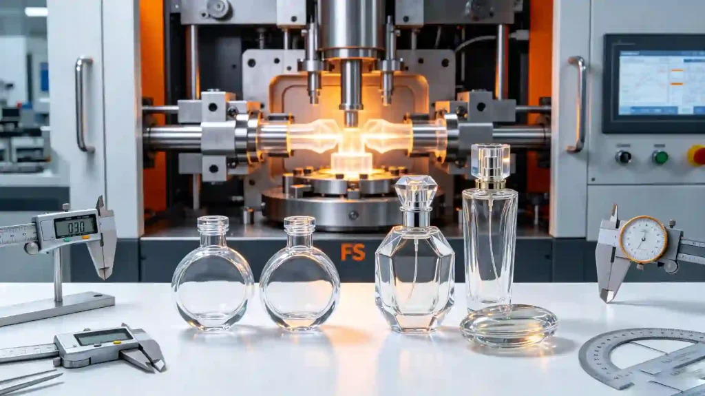
Irregular Bottle Shapes in Personal Care
The FS Platform: Four Design Differences That Address Irregular Geometry
| # | Design Feature | Why It Matters for Irregular Containers |
|---|---|---|
| 1 | Full conditioning station capacity per preform | A 4-cavity ES machine divides conditioning heat across 4 preforms. FS single-cavity applies 100% of station capacity to 1 preform per cycle — enabling longer dwell times (5–20 s) for thermal equilibration through thick or non-uniform preform walls. A 5.5mm wall PETG preform for a faceted perfume bottle requires ~14 s dwell for ±1 °C through-wall gradient. Unachievable on a 4-cavity ES at the same heat budget. |
| 2 | Rotational position-controlled preform transport | Standard ES-platform chain transport does not control the rotational orientation of preforms at blow station entry. For oval or rectangular preforms, the major axis must consistently align with the mold major axis. FS platform uses orientation-controlled transfer — eliminating the random rotational misalignment failure mode that makes defects appear sporadic on ES multi-cavity lines running non-round preforms. |
| 3 | Multi-stage blow pressure profile (3–5 stages) | Standard ES machines use a 2-stage profile (pre-blow → main blow) adequate for round bottles. FS platform supports 3–5 stages: pre-blow (4–6 kg/cm²) → intermediate (12–18 kg/cm²) → main blow (26–35 kg/cm²), with independent time and pressure control at each stage. The extended ramp allows material to begin flowing into corner geometries under low pressure before full blow force is applied — directly reducing corner wall thinning. |
| 4 | Extended mold cooling dwell accommodation | A round 200ml cosmetic bottle with uniform 1.8mm walls requires 3–5 s cooling dwell. A faceted 50ml perfume bottle with 2.5mm embossed panel zones and 1.5mm flat panels requires 6–10 s for both zones to reach dimensional stability simultaneously. FS single-cavity production has a longer inherent cycle time — accommodating this extended dwell without requiring the machine to slow below its mechanical minimum, which causes heating/conditioning timing instability. |
Output Penalty: FS vs ES — Production Planning Numbers
| Configuration | Container Example | Output (bph) | 16h Shift Output |
|---|---|---|---|
| HGA.ES-4C76 (4 cavity) | Round 200ml PET lotion bottle | 4,800 | 76,800 |
| HGA.ES-2C114.3 (2 cavity) | Oval 500ml PET shampoo bottle | 2,000 | 32,000 |
| HGA.FS-1CG130 (1 cavity) | Faceted 150ml PETG perfume bottle | 700 | 11,200 |
| HGA.FS-1CG196 (1 cavity) | Multi-faceted 1,000ml PETG cosmetic | 600 | 9,600 |
Capacity planning example: A brand requiring 50,000 units/week of a 150ml faceted PETG bottle needs a single FS-1CG130 running 80 hours/week at 700 bph to produce 56,000 units — marginally sufficient with no OEE buffer. Any downtime erodes the buffer. For this volume, plan a second machine as standby capacity or accept confirmed overtime as the recovery mechanism.
When to Request an FS Platform Assessment Before Specifying ES
Request FS platform review if any of the following apply:
| ▶Container cross-section aspect ratio exceeds 1.8:1 (oval, rectangular, or polygonal) |
| ▶Container has an angled or offset neck relative to the container centroid |
| ▶Container includes embossed depth features exceeding 1.0mm relief |
| ▶Material is PETG and any zone has a local planar stretch ratio exceeding 9× |
| ▶Container design has failed on a competitor’s ES-platform machine with unresolved root cause |
| ▶Required dimensional tolerances on any linear container dimension are tighter than ±0.15mm |
Domande frequenti
▶ Can the FS-1CG platform be configured for 2-cavity production?
▶ Is there a geometric threshold where ES multi-cavity can produce oval PETG bottles acceptably?
▶ What is the tooling lead time difference between FS and ES molds?
▶ Does the FS platform support multi-layer PCTG or PC/PETG co-injection preforms?
Complex container geometry? Start with a platform assessment.
Provide your container drawing, material specification, and target output — and receive an ES vs FS platform recommendation with mold design consultation.