
Descrizione
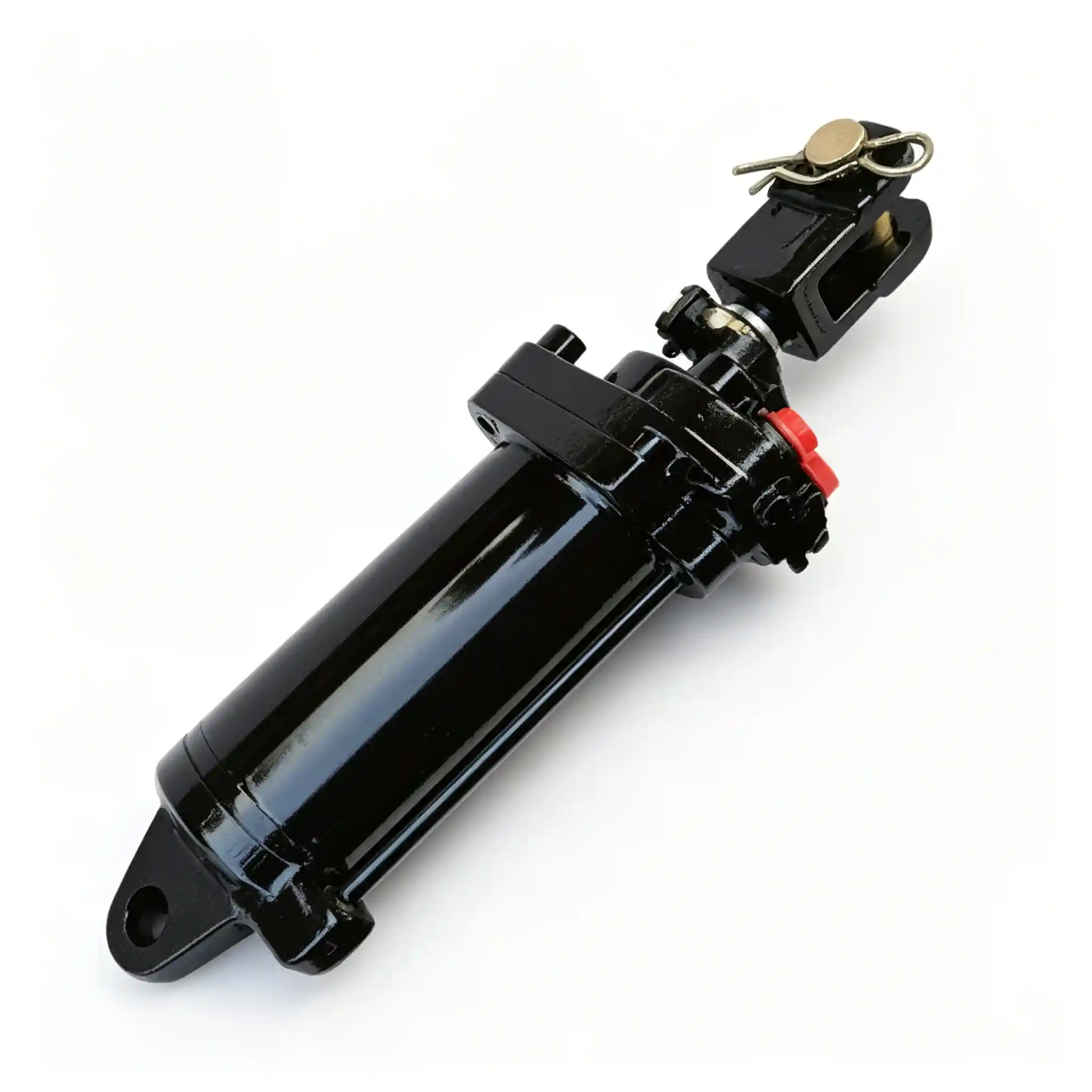
The TF1004.55.8 is a 90 mm bore tractor hydraulic lift cylinder with a 35 mm rod, 200 mm stroke, and 535 mm mounting distance. Within the 535 mm mounting distance group — which spans bore sizes from 80 mm to 120 mm — it is the only cylinder with a 90 mm bore. That makes bore measurement the single measurement that uniquely identifies this model once the 535 mm mounting distance and 200 mm stroke are confirmed.
Moving from the FT800.55A.012’s 80 mm bore to the TF1004.55.8’s 90 mm bore is a 27% increase in piston area — and therefore a 27% increase in theoretical hydraulic force at the same pressure. That is not a marginal change. A machine specified with a 90 mm bore cylinder has its hydraulic system, pump output, and lift linkage structural load all calibrated to that higher force level. The TF1004.55.8 is not simply a “bigger” version of the FT800; it serves a different machine with different design requirements.
Ever-Power supplies the TF1004.55.8 as an aftermarket replacement for agricultural tractor hydraulic lift applications. Confirm bore, stroke, and mounting distance before ordering — all three are needed to distinguish this model within the 535 mm group.
TF1004.55.8 — Technical Specifications
| Parameter | Value | Notes |
|---|---|---|
| Bore Diameter | 90 mm | Only 90 mm bore in the 535 mm mounting group; ~27% more piston area than 80 mm bore |
| Rod Diameter | 35 mm | Rod-to-bore ratio 0.39 — narrower than FT800.55A.012 (0.40) at larger bore |
| Stroke | 200 mm | Same as FT800.55A.012 and TF1204/TF1304 in the 535 mm group |
| Mounting Distance | 535 mm | Shared with FT800, TF1204/TF1304, TC2104, FS2604; pin-center to pin-center retracted |
| Extended Length | 735 mm | Pin-center to pin-center at full extension (535 + 200) |
| Applicazione | Agricultural tractor hydraulic lift systems | Confirm bore — it is the unique identifier within the 535 mm group at 200 mm stroke |
| Supplier | Ever-Power | OEM and aftermarket supply; custom specifications on inquiry |
From 80 mm to 90 mm Bore: A 27% Increase in Piston Area
Because piston area scales with the square of the radius, a 10 mm increase in bore diameter produces a disproportionate increase in force potential. From 80 mm to 90 mm:
| Bore | Piston Area | Force @ 160 bar (ref.) | Force @ 180 bar (ref.) | vs 80 mm |
|---|---|---|---|---|
| 80 mm (FT800) | 5,027 mm² | ~80.4 kN | ~90.5 kN | — |
| 90 mm (TF1004) | 6,362 mm² | ~101.8 kN | ~114.5 kN | +26.6% |
Engineering Reference Note: All force figures are theoretical calculations based on bore geometry and reference pressures. They are not rated product specifications for the TF1004.55.8. Actual force output depends on the hydraulic system’s operating pressure, valve restrictions, and circuit efficiency. No rated pressure for the TF1004.55.8 has been confirmed by Ever-Power for publication here.
A 27% increase in theoretical force is a meaningful step — equivalent to raising system pressure from 160 bar to approximately 203 bar on the same 80 mm bore cylinder. Machines designed around the 90 mm bore cylinder are built to use that additional force in their lift linkage: the lift arm dimensions, the cylinder attachment geometry, and the hydraulic system’s pressure and flow capacity are all sized accordingly.
This means the TF1004.55.8 cannot be substituted with an FT800.55A.012 to reduce cost or because one happens to be available. At the same operating pressure, the 80 mm bore cylinder delivers approximately 21% less force than the machine requires. The lift system will underperform — potentially unable to lift rated implement loads at designed operating conditions. Conversely, fitting a 90 mm bore cylinder into a system designed for 80 mm introduces higher force and flow demands that the pump and linkage were not designed to sustain.
The TF1004.55.8 Within the 535 mm Mounting Group
Five cylinders in this product range share the 535 mm mounting distance. Within that group, bore is the primary differentiator — it determines both force output and which specific machine the cylinder serves. The TF1004.55.8 is the unique 90 mm bore entry in the group.
| Model | Bore | Rod | Stroke | Rod/Bore | Force @ 160 bar |
|---|---|---|---|---|---|
| FT800.55A.012 | 80 mm | 32 mm | 200 mm | 0.40 | ~80.4 kN |
| TF1004.55.8 | 90 mm | 35 mm | 200 mm | 0.39 | ~101.8 kN |
| TF1204 / TF1304 | 100 mm | 40 mm | 200 mm | 0.40 | ~125.7 kN |
| TC2104.55JD.010 | 110 mm | 45 mm | 180 mm | 0.41 | ~152.1 kN |
| FS2604.55D4.010a | 120 mm | 60 mm | 180 mm | 0.50 | ~181.4 kN |
Two observations from this table are worth noting. First, the rod-to-bore ratio across the group sits consistently between 0.39 and 0.41 for the 80 mm through 110 mm bore cylinders — a relatively narrow band that reflects similar design intent around stiffness and connection geometry. The FS2604’s 60 mm rod at 120 mm bore (ratio 0.50) is a noticeably higher ratio, indicating a more robust rod specification for the largest bore in the group.
Second, the stroke steps down from 200 mm to 180 mm at 110 mm bore (TC2104) and continues at 180 mm for the 120 mm FS2604. The two largest-bore cylinders use a slightly shorter stroke — suggesting that the machines they serve require a somewhat more compact travel range despite their larger installation frame, or that the 535 mm mounting distance is maintained while the total body length is managed through the stroke reduction.
35 mm Rod on a 90 mm Bore: Proportioning and Practical Implications
The TF1004.55.8 uses a 35 mm rod — the same absolute diameter as the TEQ300.59.001A and QY350.59.003 (both 63 mm bore cylinders), but here paired with a 90 mm bore. The rod-to-bore ratio is 35/90 = 0.39, marginally lower than the FT800’s 0.40 at a smaller bore. In practice, the 35 mm rod on a 90 mm bore provides adequate stiffness for a 200 mm stroke in a well-aligned agricultural lift installation. The 200 mm unsupported rod length at full extension is the same as on the FT800.55A.012 — and the structural analysis follows the same reasoning as for that cylinder.
The rod diameter also governs the retraction force calculation. With a 35 mm rod, the rod cross-sectional area is approximately 962 mm² (π × 17.5²). The annular area available for retraction is 6,362 − 962 = 5,400 mm². At 160 bar reference pressure, retraction force is approximately 86.4 kN — about 85% of the extension force. That retraction-to-extension ratio shifts slightly with rod diameter: a thicker rod reduces the annular area and therefore retraction force more; a thinner rod preserves more of it.
For replacement purposes, the rod diameter determines end-connection dimensions. A 35 mm rod will have different pin-diameter requirements and clevis dimensions than the 32 mm rod on the FT800 or the 40 mm rod on the TF1204/TF1304. Even within the 535 mm mounting group, the rod end details are cylinder-specific — confirming pin diameter and connection type is essential alongside bore and stroke measurement.
200 mm Stroke: Same Travel, Different Force Budget
The TF1004.55.8 shares its 200 mm stroke with the FT800.55A.012 and TF1204/TF1304 in the 535 mm group. The implement travel range this stroke provides — scaled by the machine’s linkage ratio — is therefore the same across these three models. The difference is how much force is available to move the implement through that range.
For a machine carrying heavier implements within the same travel range, a larger bore provides the additional force at the same operating pressure. Alternatively, a machine with a smaller bore may achieve the same lift capacity by operating at higher system pressure — though this places greater demands on all hydraulic circuit components and seals. The original machine designer’s bore selection reflects the chosen balance between bore size and operating pressure for that specific application.
At 200 mm stroke and 90 mm bore, the fluid volume displaced per full extension cycle is approximately 6,362 mm² × 200 mm = 1,272 cm³. That is about 27% more fluid per cycle than the FT800’s 1,005 cm³, directly reflecting the bore area increase. The hydraulic pump must supply this additional volume within the same cycle time to maintain equivalent lift speed — which is why machines using larger bore cylinders require proportionally higher pump flow capacity.
Force at the Cylinder Rod vs Tractor Hitch Lift Capacity
At approximately 101.8 kN of theoretical extension force at 160 bar, the TF1004.55.8 generates meaningfully more force than the FT800.55A.012 at the same pressure. But the hitch lift capacity of a tractor using this cylinder is not simply 101.8 kN divided by gravitational acceleration. The linkage converts cylinder force into lifting moment at the hitch through a mechanical advantage ratio that varies with arm geometry and position through the stroke.
Rated hitch lift capacity — the published figure for a tractor — is established by standardized whole-machine testing. It is not a cylinder specification. A tractor rated to lift 2,000 kg at the hitch may use this cylinder, but the 2,000 kg figure reflects the complete mechanical system, not just the cylinder’s force output. Quoting cylinder bore and pressure as a proxy for hitch lift capacity is a technically inaccurate shortcut that should be avoided in any serious application assessment.
How to Confirm TF1004.55.8 Is the Right Cylinder
Within the 535 mm mounting group, bore measurement is the primary identifier at 200 mm stroke — only one cylinder has a 90 mm bore. Confirm mounting distance and stroke first to establish the group, then confirm bore to identify the specific model.
| Measurement | TF1004.55.8 Value | Method |
|---|---|---|
| Mounting Distance | 535 mm | Pin-center to pin-center, fully retracted; identifies the platform group |
| Stroke | 200 mm | Extended pin-pin (735 mm) minus retracted (535 mm); narrows to 200 mm subgroup |
| Bore ← unique identifier | 90 mm | Inside barrel diameter; confirms TF1004.55.8 within the 535 mm / 200 mm subgroup |
| Rod Diameter | 35 mm | Calipers on clean rod; confirms connection geometry |
| Rod-end pin diameter | To be measured | Calipers; required for end-connection compatibility |
| Base-end pin diameter | To be measured | Measure separately from rod end; may differ |
| End connection type | To be confirmed | Clevis, eye, or other at both ends |
| Port specification | To be confirmed | Thread type and size, number of ports, location |
Three-step identification within the 535 mm group:
Step 1 — Confirm 535 mm mounting distance: establishes you are in the large-frame platform group. Step 2 — Confirm 200 mm stroke: narrows to FT800 (80 mm), TF1004 (90 mm), or TF1204/TF1304 (100 mm); a 180 mm stroke points to TC2104 or FS2604 instead. Step 3 — Confirm 90 mm bore: uniquely identifies the TF1004.55.8. All three steps together give a definitive identification without ambiguity.
Hydraulic Lift Faults: Cylinder or Circuit?
On a machine using a 90 mm bore cylinder, the hydraulic circuit is handling relatively high force levels. Symptoms that appear to be cylinder failures are frequently circuit-level problems — and the larger the bore, the more pronounced the flow and pressure effects of any circuit fault.
Load drift under sustained holding
Isolate first: cap the cylinder ports with hoses removed and recheck drift. If it stops, the leakage source is in the control valve or check valve — the cylinder is holding. If drift continues with ports capped, internal piston seal bypass is the more likely cause. On a 90 mm bore cylinder, even a small leak rate past a worn piston seal produces a noticeable drift speed because the large bore area amplifies the effect of a given leak flow.
Pump cavitation or aeration noise
A 90 mm bore, 200 mm stroke cylinder requires approximately 1,272 cm³ of fluid per full extension cycle. If the pump suction is restricted, or if oil level is marginal, the pump can struggle to fill this volume at normal operating speed. Cavitation shows as a hollow whine or chatter from the pump, often accompanied by erratic cylinder motion. Check suction line condition, oil level, and filter restriction before attributing the noise to the cylinder.
Rod seal leakage after rebuild
If a freshly installed rod seal fails quickly, the cause is almost always the rod surface or the wiper seal — not the new seal itself. A 200 mm stroke rod exposes a large surface area to field contamination every cycle. Inspect the rod under good lighting for longitudinal scoring before fitting new seals. Scoring finer than the seal lip contact width can still cause leakage. A wiper seal that has hardened with age allows more contamination past it regardless of how new the rod seal is.
Reduced lift force over time
Gradual reduction in lift force over a season of use is typically pump wear, not cylinder wear. A pump losing volumetric efficiency delivers less pressure and flow as it wears, which reduces force output throughout the entire hydraulic system. A pressure gauge at the circuit test port will confirm whether the system is reaching its designed working pressure under load. If pressure is normal, internal cylinder bypass is a possibility — but address the pressure measurement first.
Requesting a Quotation for TF1004.55.8
For accurate quotation within the 535 mm mounting group, bore confirmation is the most important detail. Include all four primary dimensions in the inquiry to avoid any ambiguity.
- Reference number: TF1004.55.8
- Confirmed bore: 90 mm — the unique identifier in the 535 mm / 200 mm subgroup
- Confirmed stroke: 200 mm
- Confirmed mounting distance: 535 mm
- Confirmed rod diameter: 35 mm
- Pin diameters at rod end and base end
- End connection type at both ends
- Port thread type, size, count, and location
- Single-acting or double-acting (from port count)
- Order quantity
- Machine model and year, if known
- Working pressure, if known from machine documentation
- Photos of existing cylinder: full side view, both ends, port detail, any visible markings or damage
Frequently Asked Questions — TF1004.55.8
How much more force does the TF1004.55.8 generate compared to the FT800.55A.012?
At the same pressure, approximately 27% more. The TF1004.55.8 has a 90 mm bore (piston area ~6,362 mm²) versus the FT800’s 80 mm bore (piston area ~5,027 mm²). At 160 bar reference pressure, that translates to approximately 101.8 kN versus 80.4 kN. These are theoretical figures based on bore geometry and reference pressure — actual output depends on the system’s operating pressure and circuit conditions.
I confirmed 535 mm mounting distance and 200 mm stroke. Is that enough to identify the TF1004.55.8?
Almost, but not quite. Three cylinders in this range share both 535 mm mounting distance and 200 mm stroke: the FT800.55A.012 (80 mm bore), the TF1004.55.8 (90 mm bore), and the TF1204/TF1304 (100 mm bore). Measuring the bore is the final step that uniquely confirms which of the three you have. At 90 mm bore, the TF1004.55.8 is the only match in the group.
Can I replace the TF1004.55.8 with an FT800.55A.012 to save cost?
No. The FT800.55A.012 has a 32 mm rod versus the TF1004’s 35 mm — meaning rod-end connection geometry differs. More importantly, the 80 mm bore generates approximately 21% less force than the 90 mm bore at the same pressure. A machine designed around the TF1004.55.8 will not produce its rated lift performance with a smaller-bore cylinder at the same operating pressure. In addition, the rod diameter difference means the rod-end pin and connection dimensions will not match without bracket modification.
What does the rod-to-bore ratio of 0.39 mean for this cylinder?
The rod-to-bore ratio (35 mm / 90 mm = 0.39) describes the rod’s diameter relative to the bore. In the context of the 535 mm mounting group, ratios across the 80–110 mm bore cylinders range from 0.39 to 0.41 — a narrow band indicating similar design intent. The ratio affects retraction force (a lower ratio means more annular area and relatively higher retraction force), buckling resistance (lower ratio means a proportionally thinner rod relative to the bore), and end-connection dimensions. For a 200 mm stroke agricultural lift cylinder, a 0.39 ratio is within normal engineering practice for this application type. It does not indicate a design deficiency.
Does cylinder bore determine tractor hitch lift capacity?
No. Bore determines the force the cylinder generates at a given hydraulic pressure — which is one input to the lifting system. Hitch lift capacity is the output of the complete machine: that cylinder force, working through the lift arm geometry, mechanical advantage ratio, cylinder mounting angle, and linkage efficiency. Tractor manufacturers establish rated lift capacity through whole-machine testing to standardized protocols. The resulting figure is machine-specific and cannot be derived from cylinder bore and pressure alone.
What information should I provide for a TF1004.55.8 quotation?
The reference number (TF1004.55.8) plus confirmed bore (90 mm), stroke (200 mm), mounting distance (535 mm), and rod diameter (35 mm). Add pin diameters at both ends, end connection type, port thread specification and count, quantity, and machine model and year if known. Photos of the existing cylinder — both mounting ends, side view, port location — help confirm connection geometry before quotation. If the cylinder is damaged and bore cannot be measured directly, the machine model documentation and any body markings on the cylinder are the next-best identification sources.


