Description
Hydraulic Cylinders › Boom Swing / Side Swing Cylinders › Mini & Compact Excavators
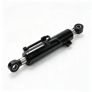
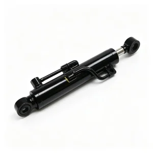
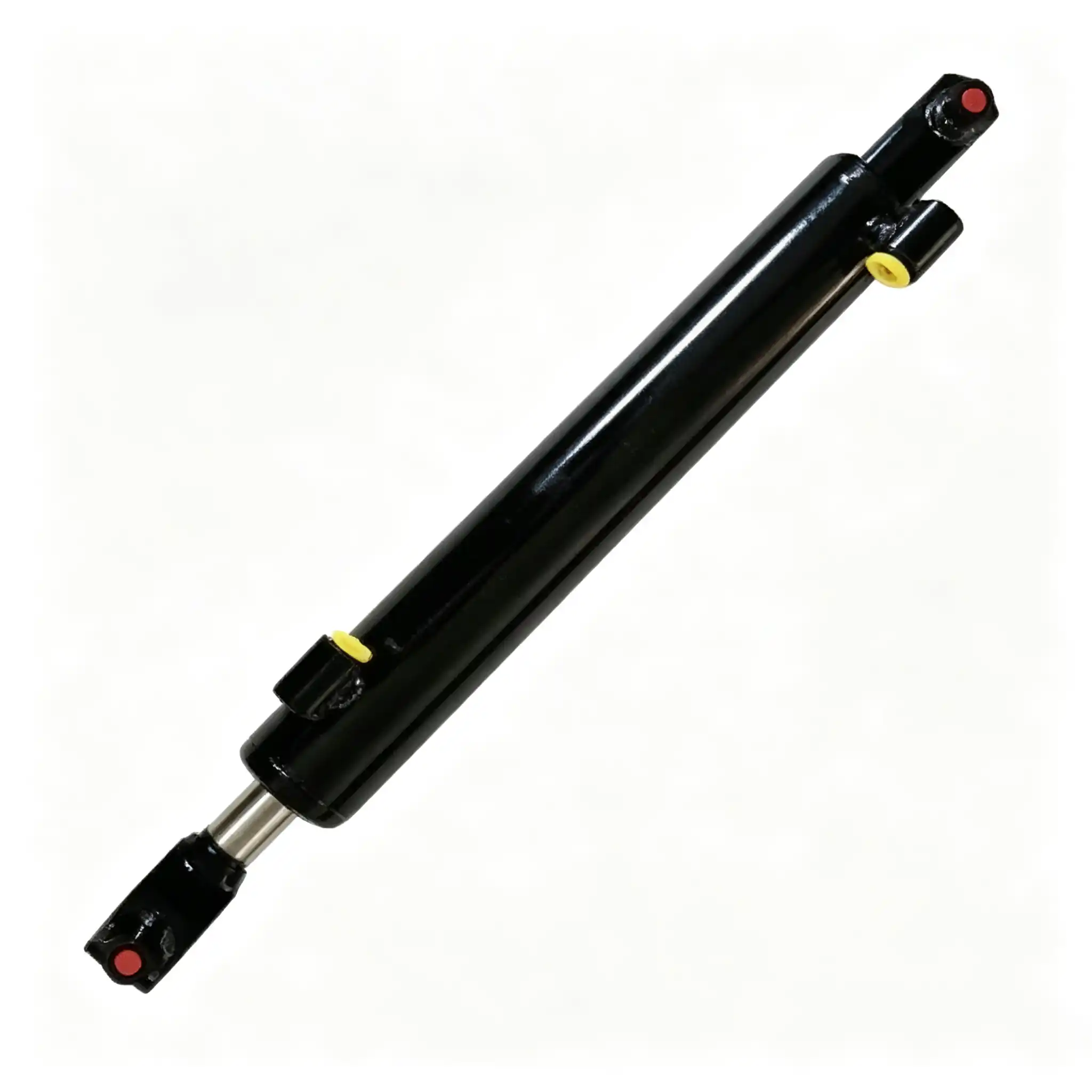
CSYG739 Boom Swing Cylinder for Mini & Compact Excavators
A 50 mm bore, 30 mm rod, 270 mm stroke boom swing cylinder engineered for the load conditions no other position on a mini excavator replicates: combined torque transmission, lateral impulse absorption, and the precision end-of-stroke control that determines whether an offset dig operation is clean or destructive.
Why the Boom Swing Cylinder Is the Most Mechanically Complex Load Path on a Mini Excavator — and the Most Frequently Misdiagnosed Failure Point
The boom swing cylinder — fitted to mini excavators with an offset or side-swing boom — performs a function that has no direct equivalent anywhere else in the machine’s hydraulic circuit. Every other cylinder on the excavator converts hydraulic pressure into linear force along a well-defined axis: the boom lifts vertically, the stick crowds horizontally, the bucket curls through its fixed arc. The swing cylinder does something structurally different. It converts that same linear hydraulic force into a rotational torque about the boom’s vertical pivot pin — swinging the entire boom-stick-bucket assembly laterally left or right relative to the undercarriage centreline, typically across an arc of 70–90°.
This geometry creates three force conditions that no other cylinder position must manage simultaneously. First, the force at the cylinder pin is not purely axial — it has a significant component perpendicular to the cylinder centreline at mid-swing positions, imposing lateral loading on both the rod-guide bearing and the barrel mounting clevis. Second, the moment arm between the cylinder force vector and the boom pivot pin changes continuously as the boom swings, creating a non-linear torque output that the operator must modulate through valve spool position rather than relying on consistent mechanical advantage. Third, the end-of-stroke condition is mechanically severe: when the operator drives the boom to full lateral offset — particularly when the bucket is loaded with material — the cylinder reaches its stroke limit and absorbs the entire kinetic energy of the swinging assembly as a hydraulic end-cushion or mechanical stop event.
In confined urban worksites — the primary operating environment for mini excavators with side-swing booms — operators use the swing function continuously to dig alongside foundations, fence lines, and retaining walls without repositioning the machine tracks. Each swing cycle begins with the boom positioned over the dig point, proceeds through a loaded crowd pass, and ends with the swing returning the loaded bucket for dump. In a 9-hour shift on a narrow trench job, the swing cylinder may complete 300–600 full-arc reversals, each ending at or near the mechanical stop position. This is the operating regime that defines the CSYG739’s specification requirements.
The CSYG739 addresses these demands through a 50 mm bore sized for adequate torque margin across the full swing arc, a 30 mm rod rated for the combined axial and lateral loads imposed by off-axis force geometry, and a 270 mm stroke matched to the boom swing pivot arm length of compact excavators in the 1.5–5 tonne class. Critically, its end-cap construction, cushioning geometry, and seal stack are specified for the high-amplitude, low-frequency end-of-stroke events that characterise swing cylinder duty — not the high-frequency, moderate-amplitude cycling of stick or bucket positions.
50 mm Bore / 30 mm Rod / 270 mm Stroke: How Each Parameter Controls Swing Torque, Arc Range, and Lateral Load Resistance
Specification rationale for procurement engineers, fleet technicians, and equipment distributors handling mini excavator parts
| Parameter | Value | Engineering Significance |
|---|---|---|
| Bore Diameter | 50 mm | Piston area ≈ 19.6 cm². Push force ≈ 39.3 kN at 20 MPa. This force, acting through the swing pivot arm length (typically 200–280 mm on compact excavators), generates the output torque that rotates the boom assembly against soil friction, attachment inertia, and wind loading on extended booms |
| Rod Diameter | 30 mm | Pull force ≈ 25.1 kN at 20 MPa for reverse swing direction. The 30 mm diameter provides adequate second-moment of area to resist the significant lateral bending component imposed on the rod at mid-arc swing positions, where the cylinder force vector is not aligned with the rod centreline |
| Stroke | 270 mm | Determines the angular range of the boom swing arc. Through the pivot arm geometry of compact excavators in this class, 270 mm of cylinder travel produces approximately 70–90° of lateral boom rotation — covering the full offset range from centreline to maximum wall-proximity dig position |
| Installation Distance | 520 mm | Pin-to-pin retracted length between the undercarriage swing frame pivot and the boom-side pivot pin. A mismatch shifts the entire swing arc off-centre — the boom cannot reach full offset on one side while over-extending mechanically on the other |
| Application Position | Boom Swing / Side Swing | Unique among all cylinder positions: force is converted to rotational torque through a pivot arm, creating combined axial and lateral loading on the rod and barrel simultaneously throughout the swing arc |
| Machine Class | Mini & Compact, 1.5–5 t | Geometry-matched to rubber-tracked mini excavators with offset or side-swing boom configurations, including zero-tail-swing and short-radius variants where boom swing is the primary means of working close to obstructions |
Swing Torque Calculation: What 39.3 kN of Cylinder Force Actually Delivers at the Boom Pivot
The torque available at the boom swing pivot is not a fixed value — it varies continuously across the 270 mm stroke as the angle between the cylinder centreline and the pivot arm changes. At the geometric position where the cylinder force vector is exactly perpendicular to the pivot arm (maximum mechanical advantage), the full 39.3 kN push force multiplied by the pivot arm length (assume 240 mm as typical) yields a maximum torque of approximately 9.4 kN·m. At the extreme end-of-stroke positions where the cylinder and pivot arm approach alignment, the mechanical advantage collapses and available torque may drop to 30–40% of this maximum despite the same cylinder force. This torque characteristic means the operator has the least swing force available precisely when it is most needed — at the extreme offset position when approaching a wall or foundation — which is why swing cylinder bore sizing must provide a generous force margin relative to the minimum torque requirement at the end-of-stroke geometry.
The pull stroke (reverse swing) uses the rod annulus area: 19.6 cm² minus the 7.1 cm² rod cross-section equals 12.5 cm² annulus, producing 25.1 kN at 20 MPa. Because the machine swings back to centreline under gravity assistance when the boom attachment is loaded, the pull stroke generally requires less force than the push stroke for most real-world operations — making the asymmetry between push and pull force acceptable from a performance standpoint while reducing the rod annulus area requirement and allowing a conservative rod diameter selection.
Rod Metallurgy, End-Cushion Design, and Lateral-Load Sealing: The Three Manufacturing Dimensions That Govern Swing Cylinder Service Life
Piston Rod: Induction Hardening Profile Chosen for Combined Axial and Bending Fatigue
The 30 mm rod begins as a precision-ground 45# medium-carbon steel bar (SAE 1045 equivalent, tensile strength ≥ 600 MPa). High-frequency induction hardening produces a surface layer of HRC 54–58 over a 1.5–2.5 mm case depth, with the core maintained at HRC 28–32. For the swing cylinder, the fatigue significance of this gradient is specifically related to combined loading: the rod experiences both axial compression/tension from cylinder pressure and a lateral bending moment from the off-axis force component throughout the swing arc. A fully through-hardened rod has high surface hardness but reduced notch toughness — at the rod-end thread root and at any surface irregularity, a brittle crack initiation risk exists under the repeated bending reversals of swing cycling. The ductile core of the induction-hardened rod provides plastic energy absorption at these stress concentrations, converting what would be brittle fracture initiation into localised plastic blunting of the crack tip.
Following induction hardening, the rod receives a 25–40 μm hard chrome layer by electroplating, achieving HV 900–1,000 surface hardness. The rod is then precision-ground and polished to Ra 0.2–0.4 μm. For the swing cylinder position, the most important property of this surface is its dimensional consistency under the lateral rod-guide bearing contact that occurs throughout the swing arc. An uneven chrome surface — with local thickness variations from inconsistent plating bath current density — creates high-spots at the rod-guide bearing contact area that produce fretting wear patterns over swing cycles, eventually generating a texture that accelerates seal lip degradation.
End-of-Stroke Cushioning: The Design Detail That Prevents Hydraulic Hammer at Full Swing
When a swing cylinder reaches the end of its stroke — the boom at maximum lateral offset — the moving hydraulic oil column must be decelerated from working velocity to zero within the remaining cylinder volume. Without a cushioning mechanism, this deceleration generates a pressure spike transmitted back through the hydraulic lines as a hydraulic hammer event. On a swing cylinder with a 270 mm stroke and a typical cylinder bore velocity of 80–120 mm/s during a normal swing pass, an uncushioned end-of-stroke impact can generate pressure spikes of 30–60 MPa in the final 20–30 mm of travel — two to three times the nominal system pressure, and well above the relief valve setting on most compact excavator hydraulic systems.
The CSYG739 end-cap geometry incorporates a conical cushion spigot at the rod-end and/or head-end positions that engages a matched bore in the end-cap approximately 15–25 mm before the stroke limit. As the spigot enters the cushion bore, the only path for the trapped oil to escape is through an adjustable needle valve or a fixed-orifice cushion circuit, which decelerates the piston progressively over this final travel zone. The deceleration force profile is exponential — gentle initial resistance followed by rapidly increasing back-pressure — which matches the natural decay of the boom’s kinetic energy as it approaches the mechanical stop. A correctly set cushion reduces the peak hydraulic hammer pressure from 30–60 MPa to 22–28 MPa, bringing the transient within the operating range of standard system components and dramatically reducing the fatigue loading on the cylinder’s end-cap welds and the boom’s swing pivot pin bearings.
Confined urban site operation: the primary use case for side-swing booms, where the swing cylinder absorbs end-of-stroke impact loads hundreds of times per shift working close to walls, foundations, and utility infrastructure
Seal Stack for Combined Axial and Lateral Loading Conditions
The rod seal in a swing cylinder operates under a loading condition that differs from all other positions: the rod is not purely aligned with the cylinder axis during operation. At mid-arc swing positions, the lateral force component on the rod creates a contact pressure asymmetry at the rod seal lip — one side of the seal circumference carries higher contact stress than the opposite side. Over thousands of swing cycles, this asymmetric loading creates uneven wear around the seal lip circumference, with the high-load sector reaching its wear limit earlier than the low-load sector. The result is a directional leak path — oil bypasses at one angular position on the seal rather than uniformly around the rod.
The CSYG739 rod seal uses a polyurethane U-cup of the specification used in NOK and SKF service kits for this bore size, with a lip geometry that maintains adequate contact pressure even when the contact load distribution is asymmetric. The seal’s lip interference is set to maintain positive sealing around the full circumference at the minimum contact pressure condition (the low-load arc sector during maximum lateral loading) — which means the high-load sector operates at a proportionally higher contact stress, but within the fatigue endurance of the polyurethane formulation. Behind the primary seal, a backup ring in a dovetail groove provides a secondary seal boundary against pressure spikes at end-of-stroke cushion events, preventing momentary pressure excursions from propagating external leakage through the primary seal before it has re-established full contact.
- Piston seals: Step-cut PTFE or polyurethane U-cup. Internal bypass at the piston in a swing cylinder causes the boom to drift laterally under the weight of the extended attachment — a hazard when working close to walls, drainage channels, or other infrastructure where uncontrolled boom movement can cause structural damage or operator injury.
- Guide rings: Fibre-reinforced PTFE guide bands at both piston and rod positions. Carry the lateral load component from off-axis swing force geometry without metal-to-barrel contact, preventing the bore scoring that would otherwise initiate piston seal bypass.
- Wiper seal: Single or dual-lip polyurethane wiper. Swing cylinders typically operate in a cleaner environment than blade cylinders, but the lateral rod movement pattern means contamination accumulated on the rod surface is smeared around the circumference rather than scraped cleanly — making wiper lip material selection as important as lip geometry.
- End-cap static O-rings: High-ACN nitrile formulation, compatible with mineral hydraulic oil and resistant to compression set at the 60–80°C oil temperatures generated during sustained swing-intensive operation on confined sites.
Torque Non-Linearity, Lateral Impulse Absorption, and Precise Swing Control: The Three Performance Demands That Separate a Specified Swing Cylinder from a Generic Bore-Match Replacement
The Torque Dead-Zone Problem: Why Swing Cylinders Fail at the Positions Operators Need Them Most
The relationship between cylinder hydraulic force and output boom torque is sinusoidal across the swing arc — it peaks when the cylinder and pivot arm are at 90° to each other and approaches zero as either end-of-stroke is reached. This creates a practical problem: at the maximum offset position — precisely where the operator needs the most force to begin crowding soil against a wall or foundation — the swing cylinder is approaching its near-zero mechanical advantage zone. Any internal piston bypass, any reduction in system pressure due to pump wear, or any oil viscosity increase from cold temperature all reduce the already-marginal torque available at this position. The consequence is a boom that hesitates or stalls when the operator tries to initiate the digging pass from maximum offset — a behaviour that operators frequently misattribute to insufficient engine power or pump pressure rather than swing cylinder internal condition.
A correctly specified swing cylinder with minimal internal piston bypass maintains the full nominal push force of 39.3 kN even at the geometrically disadvantaged end-of-stroke position, where the 30–40% torque efficiency means every available kilonewton of cylinder force is operationally significant. A cylinder with even 5% internal bypass — imperceptible in any other position on the machine — reduces available swing torque at maximum offset by a disproportionate margin, because the bypass loss is a percentage of an already-small effective force component.
Lateral Impulse Loading: What Happens When the Boom Swings Into a Hidden Obstruction
In confined trench work, the operator cannot always see what the swinging boom will contact at ground level. Root balls, buried utility pipe elbows, or protruding steel stakes can arrest the boom swing suddenly at a mid-arc position. When this happens, the hydraulic system is still delivering oil to the swing cylinder at working pressure — the cylinder is trying to extend or retract against a mechanically blocked boom. The shock load transmitted back through the linkage to the cylinder rod and end-cap is a combined axial and lateral impulse, acting simultaneously along the rod centreline and perpendicular to it through the moment arm of the blocked boom position.
This combined impulse is the most severe single loading event the swing cylinder will experience in service. The lateral component — perpendicular to the rod — loads the rod-guide bearing and the barrel mounting clevis in a direction for which they must have adequate structural reserve. At 270 mm stroke with the rod fully extended, a lateral arrest force of 5 kN generates a bending moment of 1,350 N·m at the rod-guide bearing. The 30 mm rod at this position has a section modulus of approximately 2,651 mm³, resulting in a bending stress of 509 MPa at the rod surface — approaching but not exceeding the surface yield strength of the induction-hardened chrome-plated rod at the contact zone. The rod material specification must be verified to provide this margin; a rod machined from lower-specification steel without adequate surface hardening could yield under a single severe mid-arc arrest event.
Smooth Swing Control and Operator Feedback: Why Hydraulic Precision Matters More Here Than on Any Other Cylinder
Mini excavator operators working in confined sites — alongside drainage channels, between vehicle bays, in basement excavations — rely on the swing cylinder’s response linearity to judge how close the attachment is to a structure without visual confirmation. A swing cylinder with high static friction (stiction) from a degraded wiper seal contaminating the rod seal, or from a worn rod surface that has increased seal contact pressure, makes fine boom positioning impossible: the boom either does not move or lurches several degrees when the operator commands a small input. A swing cylinder with internal bypass leaks across the piston produces the opposite problem — the boom drifts without operator input, requiring the operator to continuously correct position while also managing the digging controls. Both failure modes are disproportionately costly in confined-site work, where structural damage to adjacent infrastructure is an immediate consequence of boom position errors of even 50–100 mm.
Push Force
39.3 kN
@ 20 MPa, 50 mm bore
Pull Force
25.1 kN
@ 20 MPa, 30 mm rod
Max Swing Torque
~9.4 kN·m
At peak 90° geometry, 240 mm pivot arm
End-of-Stroke Cushion
15–25 mm
Deceleration zone; reduces peak hammer from 60 MPa to 22–28 MPa

Offset digging alongside a foundation: where swing cylinder torque linearity and end-of-stroke cushioning directly govern both productivity and the safety of adjacent structures
Installation Verification, Arc Geometry Calibration, and Maintenance Protocol for Mini Excavator Swing Cylinders
Installation Distance and Swing Arc Centering: The Alignment Check That Most Replacement Jobs Skip
The CSYG739’s 520 mm installation distance (pin-to-pin, fully retracted) positions the boom at one end of its swing arc when the cylinder is retracted, and at the opposite extreme when extended. A replacement cylinder with a different installation distance shifts the entire swing arc relative to the machine centreline — the boom may no longer reach the same maximum offset on one side, or it may over-extend the pivot arm past its mechanical stop on the other side. Before fitting, measure the retracted length of the failed cylinder from pin centre to pin centre and compare to 520 mm. If the failed cylinder has deformed from a severe impact event, refer to the machine’s service manual for the as-designed specification.
End-Cushion Adjustment After Installation: A Required Step, Not an Optional Refinement
If the CSYG739 incorporates an adjustable end-cushion needle valve, this must be set after installation to match the swing speed of the specific machine and attachment configuration. A cushion set for a bare boom will be inadequate for a boom with a hydraulic thumb or rock breaker attachment — the higher swinging mass requires more cushion resistance to decelerate within the available 15–25 mm cushion travel. To set: connect the machine to its full typical attachment load, run the engine at full throttle, and execute several full-speed swings to each stop position, adjusting the needle valve until the boom decelerates smoothly with no audible hydraulic hammer at either end. Over-tightening the cushion needle valve reduces swing speed unnecessarily; under-tightening allows hammer loading to resume. This is a 10-minute commissioning step that significantly extends the service life of the cylinder’s end-cap welds and the boom pivot pin bearings.
Maintenance Schedule Calibrated to Swing Cylinder Duty Conditions
- Daily (operator): Perform a 30-second lateral drift check at the start of each shift: with the boom at mid-arc and engine idling, release the swing control and observe boom movement over 2 minutes. Any measurable uncontrolled lateral drift indicates piston seal bypass requiring prompt assessment — in confined-site work, uncontrolled lateral boom movement is a structural damage risk, not merely a performance issue.
- Daily (visual): Inspect the rod surface for scoring from lateral contact during any mid-arc arrest events from the previous shift. A rod scored in a mid-arc position will produce asymmetric seal wear concentrated at the angular position corresponding to the score location — accelerating the directional leak pattern described in the seal engineering section above.
- 50-hour interval: Grease both swing pivot pins with NLGI #2 EP lithium grease. The swing pivot pin carries the full lateral torque reaction from the cylinder — dry pivot pin bushings allow the pin to freak under load, transmitting rotational micro-impacts directly to the cylinder clevis bore and accelerating clevis wear at a rate that no seal maintenance can offset.
- 250-hour interval: Check hydraulic oil cleanliness (ISO 4406 target: 17/15/12) and inspect the swing cylinder cushion function by executing 5 full-speed swings to each stop with the machine’s typical attachment loaded. Any audible hammer at the stop position indicates cushion needle valve readjustment or, if the valve is fully open and still hammering, a worn cushion spigot-to-bore clearance requiring cylinder attention.
- 600–1,000-hour interval: Full reseal. The swing cylinder’s seal replacement interval is longer than the stick cylinder due to lower total cycle counts, but the reseal must include inspection of the end-cap cushion geometry — the cushion spigot and bore surfaces wear over time, increasing the clearance and reducing cushion effectiveness before the seals reach their wear limit. Address both in the same service event.
- After any mid-arc arrest event: Inspect the rod visually for straightness by rolling it on a flat surface. A rod bent by even 0.5 mm permanent deflection from a severe lateral arrest load will produce a sinusoidal rod-seal contact pressure pattern that generates a circumferential leak path within 100–200 operating hours of continued use. A bent rod is not a field-repairable component — schedule cylinder replacement.
Request a Quote, Technical Drawing, or Volume Pricing for the CSYG739
Our engineering team maintains dimensional drawings, cushion specification data, seal-kit breakdowns, and cross-reference tables for the CSYG739 and 2,000+ related swing and offset cylinder part numbers across the compact excavator segment. Single-unit evaluations, regional distributor stocking programs, and OEM supply volumes are all supported.
Provide machine model, swing configuration (left/right or symmetric), quantity, and delivery port. FOB/CIF pricing within one business day.
Technical Drawing
Full dimensional drawings including cushion geometry (PDF/DWG), seal-kit part list, and cushion needle valve adjustment guide for qualified distributors and fleet accounts.
Custom Specification
Non-standard bore, stroke, cushion type, or pivot arm configuration? Submit your swing frame drawing or failed cylinder measurements for a custom quotation.
Material test reports, dimensional inspection records, and certificates of conformance available for OEM and fleet accounts. Cushion adjustment documentation included with every unit on request.