Description
Heavy-Duty 50mm Bore Baler Hydraulic Cylinder — Extended Stroke Long-Ram Series
Product Overview
High-density commercial baling operations impose fundamentally different demands on hydraulic actuators than farm-scale seasonal use. A contractor running a large-format round baler or a high-capacity big-square baler at 800 to 1,200 bales per day subjects every cylinder in the machine to cumulative load cycles that would represent several full seasons of work on a typical farm unit — compressed into a single harvest campaign. Under those conditions, a cylinder that fails on bore sizing, rod buckling resistance, or seal fatigue tolerance does not cause inconvenience; it shuts down a machine generating several hundred dollars of revenue per operating hour.
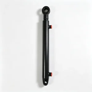
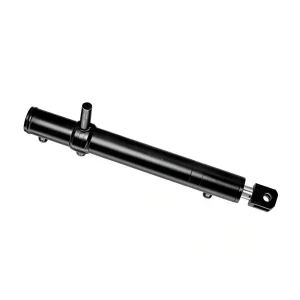
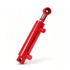
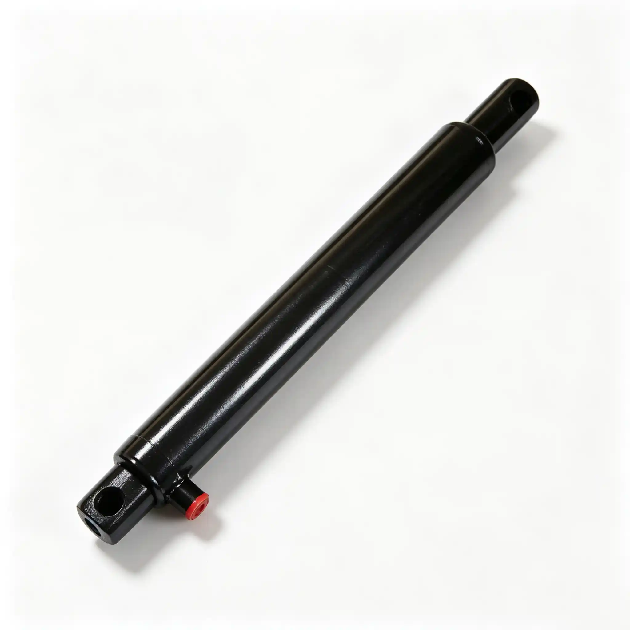
This 50mm bore baler hydraulic cylinder with a 40mm rod, 500mm stroke, and 675mm mounting distance is designed for precisely those high-load, high-cycle positions. The geometry identifies it clearly: a 500mm stroke and 675mm installed length places this cylinder in the primary compression chamber, main bale-forming roller actuation, or large-format tailgate-opening function — positions where smaller bore cylinders simply cannot generate the sustained force required without operating continuously near their pressure ceiling. The 40mm rod diameter — the same rod size used in many welded agricultural cylinders twice this unit’s price — ensures that buckling is not a design constraint even at full 500mm extension under full system pressure.
For procurement engineers sourcing heavy-duty hay baler cylinder suppliers for fleet-scale replacement programs, this series offers a dimensional match to the long-stroke actuators found on Claas, Krone, New Holland, and Fendt large-format baler platforms, while maintaining a tie-rod construction that permits field seal service without specialist workshop equipment.
Technical Specifications
| Parameter | Value | Engineering Significance |
|---|---|---|
| Bore Diameter | 50 mm | Piston area ≈ 19.63 cm²; at 160 bar delivers ~31.4 kN push force — 56% more than the 40mm bore at identical pressure |
| Rod Diameter | 40 mm | Annular area ≈ 7.07 cm²; pull force at 160 bar ≈ 11.3 kN; rod-to-bore ratio of 0.80 is the correct proportioning for long-stroke agricultural cylinders |
| Stroke | 500 mm | Covers full travel of large-format bale compression arms and major tailgate mechanisms; critical that full stroke is available without short-stroking under load |
| Mounting Distance | 675 mm | Center-to-center retracted; matches primary actuator bracket spacing on major large-format baler platforms |
| Max Working Pressure | 160 bar (rated) / 210 bar (peak) | Tested to 1.5× rated pressure per ISO 10100; peak rating accommodates pressure spikes from relief valve operation during slug feeding |
| Cylinder Type | Double-acting, tie-rod construction | Positive force in both directions; tie-rod design enables field seal replacement at harvest without workshop return |
| Rod Surface Finish | Hard chrome, Ra ≤ 0.4 μm, minimum 25 μm chrome depth | Thicker chrome specification on long-stroke rods accommodates higher cumulative seal contact cycles without surface degradation |
| Port Thread | BSP G1/2″ (SAE 3/4″-16 UNF available) | Larger port sizing reduces flow restriction and supports faster cycle times on high-flow tractor SCV circuits |
The step from a 40mm bore to a 50mm bore represents a 56% increase in piston area and therefore push force at the same system pressure. This is not a marginal upgrade — it fundamentally changes what load cases are within the cylinder’s operating envelope. A primary bale compression arm on a large-format round baler typically requires 25–30 kN of sustained hold force to maintain bale density during the final wrapping phase. A 40mm bore at 160 bar produces 20.1 kN — below this threshold, which forces the system relief valve to cycle repeatedly, generating heat, accelerating oil degradation, and causing erratic bale density. The 50mm bore at the same 160 bar produces 31.4 kN, placing the sustained compression force well within the operating range and allowing the pressure control valve to modulate normally rather than cycling between open and closed.
The 500mm stroke introduces a structural consideration that does not apply to short-stroke cylinders: rod buckling under compressive load. Euler’s critical load formula for a 40mm chrome-molybdenum steel rod at 500mm free length (assuming worst-case fixed-free end condition for a double-clevis mount) yields a critical buckling load of approximately 52 kN — more than 65% above the maximum push force this bore can generate at rated pressure. This margin is the engineering rationale for the 40mm rod specification. Reducing rod diameter to 32mm — as some budget alternatives do on long-stroke cylinders — cuts the critical buckling load to approximately 19 kN, below the cylinder’s own force output. That geometry will buckle the rod under full pressure at end of stroke, which manifests as a sudden lateral rod deflection that destroys the front bushing and rod seal in a single event.
Engineering & Design Advantages
Long-Stroke Seal Pack Geometry: A 500mm stroke places substantially greater cumulative sliding distance on rod seals per operating hour than short-stroke auxiliary cylinders. The rod seal assembly in this series uses a three-element arrangement to address this: a polyurethane primary lip seal energised by a compressed O-ring backer, a secondary polyurethane check ring that prevents lip seal extrusion under peak pressure spikes, and a PTFE-faced wiper ring at the outermost position. The check ring is the critical addition on long-stroke, high-pressure cylinders. Without it, the primary lip seal extrudes slightly into the annular clearance between rod and seal housing during peak pressure events, causing a permanent deformation that creates a micro-leak path. The check ring physically blocks this extrusion path while adding negligible friction to rod travel.
Piston Seal Configuration for High-Force Applications: The piston seal on this 50mm bore cylinder is a double-acting composite assembly: a central cast-iron wear ring maintains rod-to-bore concentricity and carries the radial side-load imposed when the linkage geometry is not perfectly in-line with the cylinder axis (which is normal in baler mechanism designs). The hydraulic sealing function is handled by two opposing PU lip seals, one facing each pressure port. This separation of load-carrying and sealing functions prevents the seal from being mechanically overloaded by side forces — a root cause of premature piston seal failure in single-element piston seal designs used in budget cylinders.
Bore Honing Specification: The 50mm bore is finish-honed to a cross-hatch surface at Ra 0.6–0.8 μm. This surface finish is deliberately coarser than a mirror-polished bore. The cross-hatch pattern retains a microscopic film of hydraulic oil between seal contact cycles, which reduces dry-start friction and seal wear during the first pressure stroke after a machine has sat overnight. A bore honed too smooth — Ra below 0.4 μm — fails to retain this oil film, leading to higher static friction (stick-slip) at the start of each work cycle, which manifests as jerky linkage movement and accelerated seal lip fatigue.
Cushioning on Long-Stroke Cylinders: At 500mm stroke, a piston travelling at typical baler cycle speeds of 0.3–0.5 m/s carries significant kinetic energy at end of stroke. Without cushioning, this energy is transferred to the end cap and connected structure as an impact load. The end cushions in this cylinder engage at approximately 30mm before end of stroke, decelerating the piston smoothly over the remaining travel. The cushion geometry is sized to dissipate full kinetic energy at maximum rated flow, so cushioning performance does not depend on the operator reducing tractor SCV flow — the cylinder handles deceleration internally regardless of upstream flow rate.
External Corrosion System on a Large-Format Cylinder: The larger surface area of this cylinder’s barrel and end caps increases the total area requiring corrosion protection. The two-stage phosphate-plus-powder-coat system applied to the 40mm series is retained, but the powder coat thickness specification is increased to a minimum of 100 μm on the barrel exterior — 25% thicker than the standard specification — to account for the higher mechanical abrasion exposure that comes with a cylinder mounted in the lower sections of large baler frames, where contact with soil, stones, and crop stems is frequent.
Application Specifics
The 50mm bore / 40mm rod / 500mm stroke configuration addresses the highest-load, longest-travel positions in large-format baling equipment. The primary functional positions where this cylinder’s specifications are required include:
- Main bale chamber compression (large round balers, 1.5m+ bale diameter): The compression arm must hold 25–30 kN continuously during the final bale diameter phase while the wrapping cycle completes. The 50mm bore provides the force margin to do this at normal operating pressure rather than at or above relief valve setting.
- Primary tailgate opening on large round balers: A 1.5m round bale of dense hay or silage weighs 500–700 kg. The tailgate mechanism must lift and hold the rear half of the bale chamber while the bale ejects. The 500mm stroke covers the full tailgate arc on baler designs with large-radius pivot geometry, and the 50mm bore provides the force to lift the tailgate against both gravity and the residual compression of the bale against the tailgate during ejection.
- Bale kicker and ejection actuator (square balers): High-output square balers use a hydraulic kicker to push completed bales off the bale chute. The 500mm stroke covers the full ejection travel on large chute designs, and the 40mm rod prevents rod flex that would cause the kicker plate to misalign and jam bales against the chute sidewall.
- Density control hydraulic ram (variable-chamber round balers): Variable-chamber designs use a long-stroke hydraulic cylinder to vary the belt tension and therefore bale density on the fly. The 500mm stroke covers the full range of belt tension adjustment, and the 50mm bore provides enough force authority for the density control system to respond quickly to changes in crop feed rate without hunting around the setpoint.
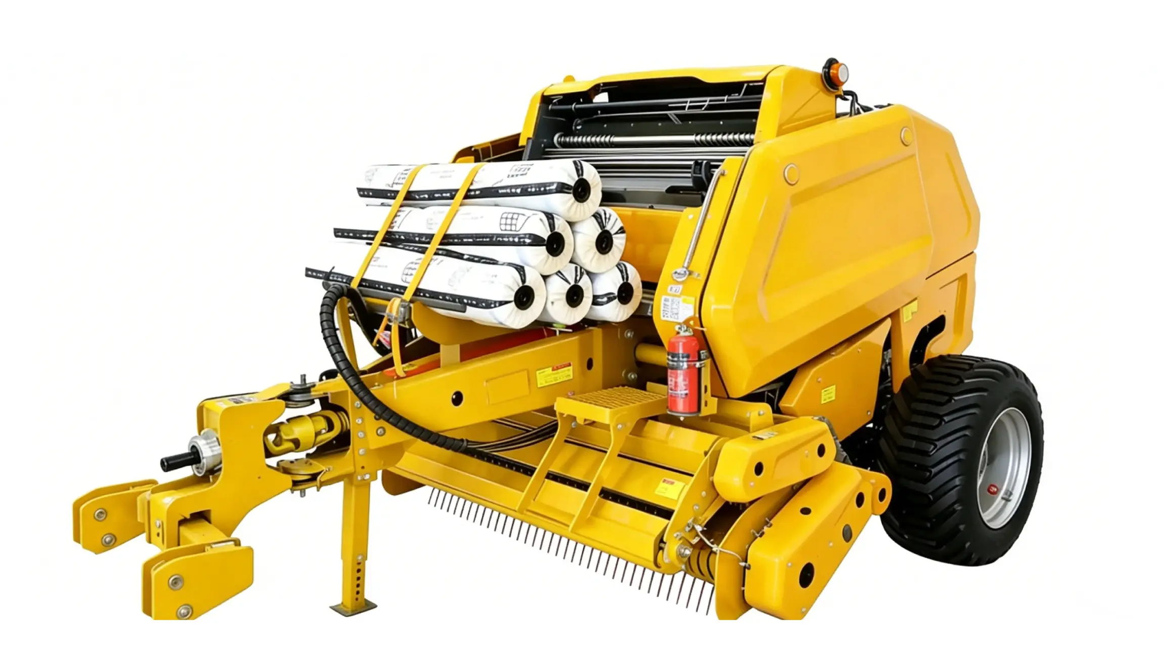
A note specific to variable-chamber density control applications: the cylinder in this position is rarely at a fixed end-of-stroke position during normal operation. It spends most of its working life at intermediate positions under sustained load — a duty cycle that is harder on seals than simple extend-retract cycling. The compound piston seal assembly described above is specifically selected for this mid-stroke sustained load pattern, as standard single-element piston seals in this position show consistent bypass leakage within 200 operating hours on variable-chamber applications.
Quality Control & Testing

The extended stroke and larger bore of this series require an adjusted quality control protocol compared to short-stroke auxiliary cylinders. The following procedures apply:
- Rod straightness verification: Every 40mm rod is measured for straightness along its full 500mm+ length before assembly, using a V-block and dial gauge at 100mm intervals. Acceptance criterion: total indicator runout ≤ 0.15mm over the full rod length. Rods failing this check are rejected regardless of surface finish — a bent rod that meets surface roughness specification will still destroy the front bushing and rod seal within the first operating season.
- Full-stroke low-pressure run-in: After assembly, each cylinder is cycled 10 times at 10 bar through full 500mm stroke before pressure testing. This run-in seats the new seals against the bore and rod surfaces, reducing the risk of initial seal weeping that can occur when new PU seals are compressed for the first time at full pressure before they have conformed to their mating surfaces.
- Sustained static pressure hold: Both chambers are individually pressurised to 240 bar (1.5× rated) for a 5-minute hold — longer than the standard 3-minute hold for short-stroke units, to expose any slow weep paths through the seal system that may not manifest immediately. Zero pressure drop required for pass.
- Extended cycle life testing (batch sample): Minimum 5% of each production batch undergoes 100,000 full-stroke cycles at rated pressure. At 500mm stroke, this represents approximately 100km of total rod travel — equivalent to more than five seasons of commercial contractor baling use. Acceptance criteria after 100,000 cycles: piston bypass leakage below 3 ml/min at rated pressure; rod seal external leakage zero; bore ovality increase below 0.025mm; rod chrome surface Ra increase below 0.1 μm.
Maintenance & Troubleshooting Guide
Long-stroke cylinders operating in primary load positions on large commercial balers have specific maintenance requirements that differ from shorter auxiliary cylinders. The guidance below addresses the failure modes most commonly seen in the field on this category of cylinder.
1. Monitoring for Piston Bypass — the Invisible Failure Mode
Unlike rod seal failure, which produces visible external oil leakage, piston seal bypass leaks internally — oil crosses from the high-pressure side of the piston to the low-pressure side without leaving the cylinder body. The external symptom is loss of holding force: the bale compression arm drifts under load, bale density becomes inconsistent, or the tailgate sinks slowly after being opened. By the time drift is noticeable to the operator, the piston seal is typically past its useful life and is allowing 20–50 ml/min of bypass flow. The practical detection method without removing the cylinder: block the return port (the low-pressure port when the cylinder is fully extended under load), apply full system pressure to the extend port, and monitor whether the rod continues to creep slowly inward. If it does, piston bypass is confirmed. This test takes under two minutes and can be performed in the field without special equipment. Perform it at the start of each season and at the midpoint of any high-output campaign.
2. Managing Thermal Expansion on Long-Stroke Cylinders
At 500mm stroke, thermal expansion of the rod during operation is non-trivial. Chrome-molybdenum steel expands at approximately 12 μm per metre per degree Celsius. A 40mm diameter rod at 500mm exposed length will expand roughly 0.6mm in length between a cold start at 5°C and normal operating temperature at 60°C. In a rigid mounting arrangement, this thermal growth applies a compressive pre-load to the rod — which is why clearance in mounting pin bores must be maintained and grease renewal is not optional. A dry, seized mounting pin that cannot accommodate this thermal growth concentrates the expansion force at the clevis threads, eventually cracking the clevis eye or thread runout. Check mounting pin clearance (0.1–0.3mm nominal) every 200 operating hours and replace pins showing oval wear exceeding 0.5mm.
3. Hydraulic Oil Viscosity Selection for Long-Stroke, High-Cycle Applications
ISO VG 46 is the standard recommendation for agricultural hydraulic circuits, and it is correct for moderate-duty use. Commercial contractors running 1,000+ bales per day should consider ISO VG 68 hydraulic oil if ambient temperatures during harvest consistently exceed 25°C. At high cycle rates, the hydraulic oil temperature in a working baler circuit can reach 70–80°C, at which point VG 46 oil falls below its designed viscosity range and provides insufficient film thickness to protect pump and cylinder surfaces. VG 68 maintains adequate viscosity through 85°C ambient fluid temperature and is compatible with all PU and PTFE seal materials used in this cylinder series. Do not use VG 68 in cold climates (below 0°C start temperatures) without an oil pre-heat system — the higher viscosity at cold start increases pressure drop across the hydraulic circuit and can cause pump cavitation during the first minutes of operation.
4. Field Seal Replacement Protocol for Long-Stroke Cylinders
The 500mm stroke places the fully-extended rod well outside the cylinder body during seal replacement work. Before disassembly, retract the cylinder fully and block the circuit in the retracted position — a cylinder with a partially extended rod that drops during disassembly can cause serious injury. Use a proper tie-rod wrench — not an adjustable wrench — to remove the rear end cap first. Withdraw the piston and rod assembly by pulling from the rear, not pushing from the front port. Lay the rod assembly on a clean padded surface (a rubber mat works well) to avoid chrome surface damage. The piston seal assembly on this series uses a snap-ring retained piston construction; the piston can be removed from the rod using a strap wrench without thread damage. Inspect the piston bore face and piston groove dimensions before installing new seals — a worn or scratched piston groove will allow new seals to extrude or roll during re-pressurisation. Seal kits include a full illustrated instruction sheet with all torque specifications.
Frequently Asked Questions
Q: This is described as a heavy-duty hay baler cylinder. What working pressure and cycle rate does “heavy duty” specifically mean in your test protocol?
In our test protocol, heavy duty is defined by three parameters: rated working pressure of 160 bar with a 210 bar peak allowance, a minimum 100,000 full-stroke cycle life at rated pressure before seal inspection, and a static pressure hold to 240 bar for 5 minutes with zero measured pressure drop. These figures are not marketing descriptors — they correspond to the actual loads and cycle counts generated by commercial baling contractors operating large-format balers at 800–1,200 bales per day across a 6–8 week harvest season. Any supplier claiming heavy-duty rating without specifying these three parameters is using the term without a verifiable technical basis.
Q: Can this cylinder be used on a silage baler running high-moisture crop? Are the seals compatible with silage acids?
Yes, with a qualification. The polyurethane seals and PTFE wiper used in this cylinder are chemically resistant to the organic acids (primarily lactic acid, pH 3.8–4.5) present in wilted silage crop. The chrome rod surface and powder-coat barrel finish are similarly resistant. The qualification applies to the hydraulic oil: if crop juice enters the hydraulic circuit — which can happen through a damaged hose or fitting on a machine making haylage with high moisture content — even a small amount of water contamination causes rapid oil emulsification and accelerated seal degradation that no seal material can prevent. On silage baling applications, inspect all hydraulic hose connections at every refuelling stop and check hydraulic oil colour weekly. Fresh oil is amber-clear; emulsified oil is milky and must be drained and replaced immediately along with the filter.
Q: What is the correct mounting orientation for this cylinder — horizontal, vertical, or angled?
This cylinder is designed to operate in any mounting orientation — horizontal, vertical, or inclined — without modification. The seal system is not orientation-dependent. The only orientation consideration for long-stroke cylinders is the effect of gravity on the rod when the cylinder is mounted with the rod pointing downward (rod-down, vertical). In this position, gravity assists the extend stroke and resists the retract stroke, which affects cycle speed and means the retracting force available is the pull force (rod area × pressure) rather than push force. Confirm that the pull force at your system operating pressure is sufficient for the retract load before specifying a rod-down vertical installation. If you provide your mounting geometry and system pressure, our engineering team will confirm the force balance.
Q: I need to source replacement cylinders for a fleet of 12 large round balers for next season. What lead time and minimum order quantity should I plan for?
For fleet-scale procurement — typically defined as 10 units or more of a single specification — we recommend a minimum 6-week lead time from order to delivery for standard configurations. Custom pin sizes, non-standard port threads, or modified clevis dimensions require an additional 2–3 weeks for tooling. There is no formal minimum order quantity for standard configurations, but orders of 5 or more units from the same specification draw from dedicated batch production rather than stock, which ensures dimensional consistency across the fleet. Contact our sales team with your fleet size, baler make and model, and the four key cylinder dimensions (bore, rod, stroke, mounting distance) to receive a fleet supply quotation with pricing, lead time, and available documentation for your procurement records.
Request Fleet Quotation or Technical Support
Our engineering team handles fleet replacement programs, OEM supply agreements, and custom-dimension cylinder specifications for agricultural machinery manufacturers. Provide your cylinder dimensions, annual volume, and target delivery schedule and we will respond within one business day with a full technical and commercial proposal.
Website:
ever-powers.com
Email:
[email protected]