Descrizione
Hydraulic Cylinders › Side Swing Cylinders › Mini & Compact Excavators
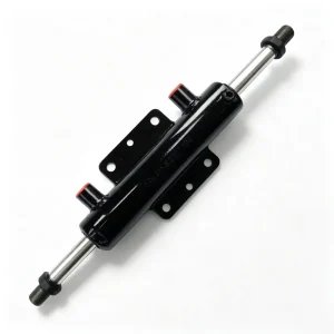
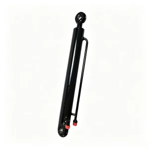
Side Swing Hydraulic Cylinder for Mini & Compact Excavators — 50 mm Bore, 430 mm Stroke
A long-stroke side swing hydraulic cylinder with 50 mm bore, 30 mm rod, and 430 mm stroke — engineered for mini excavators requiring a wider lateral boom arc, greater offset reach from a fixed track position, and the structural resilience to absorb end-of-stroke impulse loads across a longer travel path than standard swing cylinders.
What a 430 mm Stroke Actually Changes About Side Swing Performance — and Why Standard Swing Cylinders Fall Short on Wide-Arc Applications
The majority of mini excavators with side-swing boom configurations leave the factory with swing cylinders in the 250–300 mm stroke range, producing a lateral boom arc of approximately 70–90°. That arc is adequate for digging alongside a single wall or foundation line in a standard trench configuration. It is not adequate for machines required to work in wider offset scenarios: excavating beneath a road surface from one fixed track position, clearing material from both sides of a utility corridor without repositioning, or operating a hydraulic breaker or auger at maximum lateral reach without machine relocation.
This side swing hydraulic cylinder’s 430 mm stroke addresses that constraint directly. Through the pivot arm geometry of compact excavators in the 1.5–5 tonne class, 430 mm of linear cylinder travel produces a lateral boom arc in the range of 100–120° — a 25–35% wider working envelope than a standard 270–300 mm swing cylinder on the same machine. The practical consequence is measurable: a machine fitted with this cylinder can dig a wider trench pass without track relocation, position a hydraulic breaker against two parallel wall faces from a single standing position, or clear a wider corridor of material in a single swing sequence. Each repositioning manoeuvre avoided on a confined urban site saves 3–8 minutes of cycle time and eliminates the ground disturbance and utility risk associated with tracked machine movement in service-dense environments.
The longer stroke also changes the cylinder’s structural engineering requirements in ways that are not immediately obvious from a simple bore specification comparison. A 430 mm stroke cylinder with a 30 mm rod has a higher slenderness ratio than a 270 mm stroke cylinder with the same rod diameter — the extended rod is more susceptible to buckling under axial compressive loading and to permanent deflection under the lateral bending moments imposed by the off-axis force geometry of side swing operation. These are not theoretical concerns: field failures of long-stroke swing cylinders in the replacement parts market are predominantly rod deflection events and barrel-to-end-cap weld fatigue cracks, not seal failures. This cylinder is specified to address both structural failure modes, not only the hydraulic sealing performance that dominates shorter-stroke cylinder engineering.
The 670 mm installation distance (pin-to-pin retracted) reflects the longer physical package required to accommodate the 430 mm stroke within a standard bore class. This dimension is the primary fitment reference for procurement — it must be verified against the machine’s swing frame geometry before ordering, as it defines both the retracted boom position and the swept arc relative to the machine centreline.
50 mm Bore / 30 mm Rod / 430 mm Stroke: Engineering Rationale for a Long-Stroke Side Swing Configuration
Specification analysis for procurement engineers, equipment distributors, and fleet technical managers handling compact excavator swing cylinder sourcing
| Parameter | Value | Engineering Significance |
|---|---|---|
| Bore Diameter | 50 mm | Piston area ≈ 19.6 cm². Push force ≈ 39.3 kN at 20 MPa. Identical bore to shorter swing cylinder variants, maintaining compatibility with the machine’s existing hydraulic circuit flow and pressure ratings while the longer stroke extends the arc range |
| Rod Diameter | 30 mm | Pull force ≈ 25.1 kN at 20 MPa. At 430 mm full extension, the rod slenderness ratio is higher than on 270 mm stroke variants — requiring the induction-hardened surface and ductile core to work together to resist both buckling under axial load and bending under lateral swing force components |
| Stroke | 430 mm | Produces a lateral boom arc of approximately 100–120° through typical compact excavator pivot arm geometry — 25–35% wider than standard 270–300 mm swing cylinders. Enables wider trench-pass coverage and dual-wall working from a fixed track position |
| Installation Distance | 670 mm | Pin-to-pin retracted length. Approximately 150 mm longer than standard 520 mm swing cylinders — confirm swing frame pivot spacing before ordering. This dimension sets the boom’s neutral (centreline) position relative to the machine’s track width |
| Application Position | Side Swing (Wide Arc) | Long-stroke variant for wide-offset applications: dual-wall utility work, road-surface excavation without repositioning, wide-body demolition clearance, and auger/breaker operation at extended lateral positions |
| Machine Class | Mini & Compact, 1.5–5 t | Matched to rubber-tracked mini excavators with extended side-swing boom frames designed to accept longer-stroke swing cylinder packages. Verify swing frame pivot spacing matches 670 mm installation distance |
How 430 mm of Stroke Translates to a Wider Working Envelope — and the Structural Trade-offs That Come With It
On a compact excavator with a boom swing pivot arm of 240 mm effective radius, the relationship between cylinder stroke and lateral arc is approximately 1 mm of stroke per 0.24° of boom rotation at mid-arc (90° geometric efficiency). A 270 mm stroke cylinder therefore produces roughly 65° of usable arc at peak efficiency — less at the stroke extremes where mechanical advantage falls. A 430 mm stroke cylinder through the same geometry produces approximately 103° of usable arc, covering working positions that require the machine to be repositioned with a shorter cylinder.
The trade-off is mechanical: at 430 mm full extension, the 30 mm rod is exposed across a significantly longer unsupported span than at 270 mm. The Euler critical buckling load for a 30 mm rod of this material at 430 mm free length is approximately 85–95 kN — well above the cylinder’s 39.3 kN maximum push force, providing a buckling safety factor of approximately 2.2 to 2.4. This margin is adequate but requires that the rod material specification, heat treatment depth, and chrome layer integrity are all maintained to design standard. A rod with surface corrosion pitting, chrome layer delamination, or subsurface hardening voids reduces this margin in ways that are not visible until a sudden buckling failure occurs under a high-crowd load at full swing extension.
The hydraulic oil volume displaced per full stroke is also proportionally larger: at 430 mm stroke and 19.6 cm² piston area, one complete extension requires approximately 843 cm³ of oil flow — roughly 60% more than a 270 mm stroke cylinder of the same bore. In practical terms this means the swing movement is slower at the same pump flow rate, or requires higher pump flow to match the swing speed of a shorter-stroke cylinder. Machine operators transitioning from a standard swing cylinder to this long-stroke variant on a modified machine should expect a measurable reduction in swing speed unless the hydraulic valve spool or flow control is adjusted accordingly.
Long-Stroke Rod Metallurgy, End-of-Stroke Cushioning, and Lateral-Load Seal Specification: Where This Cylinder Must Outperform a Generic 430 mm Bore-Match Replacement
Rod Engineering for High Slenderness Ratio Service
The 30 mm rod is machined from 45# medium-carbon steel (SAE 1045 equivalent, minimum tensile strength 600 MPa). High-frequency induction hardening produces a surface layer at HRC 54–58 over a case depth of 1.5–2.5 mm, with the core remaining at HRC 28–32. For the 430 mm stroke configuration, the ductile core is more structurally significant than for shorter-stroke swing cylinders. As the rod approaches full extension under a lateral force component from the off-axis swing geometry, the combined axial and bending load at the rod-guide bearing creates a stress state that a fully through-hardened rod — with its reduced notch toughness — could not sustain through repeated swing cycles without initiating a fatigue crack at the rod-end thread root or at a chrome surface defect.
The hard chrome plating layer of 25–40 μm provides HV 900–1,000 surface hardness and is applied uniformly across the full rod working length — the entire 430 mm zone that passes through the rod-seal and wiper-seal contact faces. Uniformity of chrome thickness across this longer working length is a manufacturing quality issue that is more significant for 430 mm rods than for 270 mm variants: inconsistent plating bath current density over a longer rod produces local high-spots and low-spots in the chrome layer that create axial variation in the rod’s effective diameter. These variations cause the seal lip to experience alternating high and low contact pressure as the rod passes through — accelerating seal lip fatigue at the transition zones between chrome thickness bands. After plating, the rod is precision-ground to Ra 0.2–0.4 μm across the full working length, correcting any chrome thickness variation and establishing the uniform surface finish that the polyurethane rod seal requires for consistent contact pressure distribution.
End-of-Stroke Cushioning on a 430 mm Stroke Cylinder: Higher Kinetic Energy Demands More Effective Deceleration
The kinetic energy of the swinging boom assembly at end-of-stroke is proportional to the square of its velocity, not its displacement. A longer stroke does not in itself increase kinetic energy — but it gives the operator more travel distance in which to accelerate the swing before the cylinder reaches its stop, meaning that an aggressive operator can arrive at the stroke limit with a higher boom velocity than is possible with a shorter-stroke cylinder. At typical compact excavator swing velocities of 80–130 mm/s at the cylinder rod, the oil column deceleration in the final 20–30 mm of travel without a cushion mechanism generates a pressure spike of 35–70 MPa — above the system relief valve setting and above the rated pressure of standard hydraulic hose assemblies.
The end-of-stroke cushion on this cylinder uses a conical spigot geometry at the rod-end that engages the end-cap cushion bore in the final 20–25 mm of travel. Oil trapped in the cushion pocket escapes only through the needle valve orifice, producing a progressive deceleration force that absorbs the boom’s kinetic energy over the cushion travel distance rather than instantaneously at the mechanical stop. Correctly adjusted, the cushion brings the peak transient pressure down to 22–30 MPa — within the continuous operating rating of standard system components — while allowing the final approach to the stroke limit at near-zero velocity. The cushion needle valve is accessible from the cylinder exterior for field adjustment without disassembly: a critical serviceability feature given that cushion adjustment requirements change when the boom attachment changes (a hydraulic breaker has significantly higher swinging inertia than a bare bucket).
Seal Stack: Polyurethane Primary Seals With Asymmetric-Load Compensation for Wide-Arc Swing Geometry
The rod seal is a polyurethane U-cup of the formulation used in NOK and SKF service kits for this bore class. The functional requirement unique to side swing cylinders — that the seal must maintain consistent contact pressure around its full circumference even when the rod is under a lateral bending load from the off-axis force geometry — is addressed through the seal’s interference specification. The lip interference is set to maintain positive sealing at the minimum contact pressure sector (the side of the seal opposite the bending load direction) while the maximum contact pressure sector remains within the polyurethane material’s endurance limit across the expected service life.
On a 430 mm stroke cylinder, the rod-seal contact zone travels 430 mm of rod surface with each stroke — 60% more than a 270 mm cylinder. This means the rod surface condition across the full 430 mm working length is equally critical to seal life: a chrome defect at 380 mm from the rod tip — in the retracted zone that rarely passes through the seal on a shorter-stroke cylinder — will contact and damage the seal lip on every full extension stroke on this long-stroke variant. The full-length chrome application and full-length precision grinding are therefore not manufacturing overhead on this cylinder; they are functional requirements.
- Piston seals: Step-cut PTFE or polyurethane U-cup. Internal piston bypass on a wide-arc swing cylinder causes lateral boom drift across a larger angular range than on a standard cylinder — a proportionally greater hazard in confined-site and adjacent-structure work where the boom’s lateral position must be precisely held.
- Guide rings: Fibre-reinforced PTFE guide bands at piston and rod positions. The lateral load component from wide-arc off-axis swing geometry is higher at extreme arc positions than on shorter-stroke cylinders — the guide ring’s load-carrying capacity must accommodate the proportionally larger lateral force at 100–120° arc extremes.
- Wiper seal: Dual-lip polyurethane wiper. The longer rod working length increases the total surface area that the wiper must protect from contamination ingress — maintaining wiper lip condition across the full 430 mm of rod exposure is a more significant maintenance variable than on standard-stroke swing cylinders.
- Backup ring at rod seal: PTFE or nitrile O-ring in a dovetail groove behind the primary rod seal captures any oil that migrates past the primary under cushion pressure spikes at end-of-stroke — preventing momentary pressure events from reaching external surfaces and creating the appearance of a seal failure during normal cushioned operation.
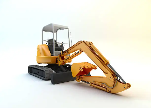
Wide-arc side swing operation: where a 430 mm stroke cylinder covers working positions that require a standard 270 mm cylinder machine to reposition tracks — eliminating repositioning time in confined urban sites
Wide-Arc Torque Geometry, Extended-Stroke Buckling Margins, and End-of-Stroke Impulse Management: The Structural Engineering Priorities of a 430 mm Swing Cylinder
Torque Output Across a 100–120° Arc: Where Mechanical Advantage Collapses and Force Reserves Become Critical
The sinusoidal relationship between cylinder force and pivot torque — peaking at the 90° geometry position and approaching zero at both stroke extremes — is more consequential on a 100–120° arc cylinder than on a 70–90° arc cylinder. A wider arc means the boom spends proportionally more of its working range in the low-mechanical-advantage zones near each stroke extreme. At the extreme 110–120° offset position, the mechanical advantage factor may drop to 15–25% of its mid-arc peak — meaning that only 6–10 kN of the cylinder’s 39.3 kN push force is converted to useful swing torque. Any piston seal bypass, pump pressure loss, or oil viscosity increase from cold temperature reduces this already-marginal force contribution at precisely the position where the operator is trying to initiate a dig pass at maximum lateral offset.
This geometric reality sets a minimum standard for piston seal integrity that is more demanding than for a standard-arc swing cylinder. Zero internal bypass at the piston is the correct specification target — not because a small bypass would cause visible oil loss, but because the 50 kPa pressure drop across a partially bypassed piston seal reduces effective push force by a percentage that translates to a proportionally larger torque reduction at the low-mechanical-advantage end-of-arc position. An operator who cannot understand why the boom lacks swing authority at full offset — when the machine is otherwise performing normally — is typically experiencing exactly this combination of geometric disadvantage and partial piston seal bypass.
Buckling Safety at Full 430 mm Extension Under Combined Axial and Lateral Loading
The Euler critical buckling load for a pin-ended column with a 30 mm solid circular cross-section and 430 mm free length is P_cr = π²EI / L² = π² × 206,000 × 39,761 / 430² ≈ 87,400 N ≈ 87.4 kN. Against the maximum cylinder push force of 39.3 kN, this provides a buckling safety factor of approximately 2.2. This margin is adequate for pure axial loading but must be evaluated against the actual combined loading condition: when the cylinder is at full extension in a wide-arc position with the boom carrying a loaded bucket, the lateral force component from off-axis swing geometry adds a destabilising bending moment that effectively reduces the available buckling safety factor. At a lateral force of 2 kN at the pivot pin — modest by excavator standards — and with 430 mm extension length acting as the moment arm to the rod-guide bearing, the combined equivalent axial load can increase by 15–20% above the pure hydraulic force, bringing the effective safety factor to approximately 1.8–1.9.
This safety factor is maintained only with the rod in straight, undamaged condition. A rod with 0.3 mm of permanent deflection — invisible to casual inspection — creates an initial eccentricity that reduces the critical buckling load by a factor dependent on the eccentricity-to-radius ratio. For a 30 mm rod with 0.3 mm eccentricity, this reduction can be 8–12%, bringing the safety factor on a combined-load scenario into the range of 1.6–1.7. Still above 1.5 — a typically accepted minimum for structural components — but with no remaining margin for additional degradation. Rod straightness inspection at each maintenance interval is therefore a structural safety check on a long-stroke swing cylinder, not merely an aesthetic quality assessment.
Push Force
39.3 kN
@ 20 MPa, 50 mm bore
Pull Force
25.1 kN
@ 20 MPa, 30 mm rod
Lateral Arc
100–120°
vs. 70–90° for standard 270 mm stroke
Buckling Safety Factor
~2.2
Pure axial at full extension; requires straight rod to maintain
Oil Vol. per Stroke
843 cm³
60% more than 270 mm stroke variant — affects swing cycle speed

Long-stroke swing in utility corridor excavation: covering both sides of a service trench from a single track position — the productivity advantage that justifies the 430 mm stroke specification
Installation Verification, Hydraulic Flow Adjustment, and Maintenance Protocol for Long-Stroke Side Swing Cylinders
Swing Frame Pivot Spacing: The Critical Measurement That Differs From Standard Swing Cylinder Installations
The 670 mm installation distance of this cylinder is approximately 150 mm longer than the 520 mm of standard compact excavator swing cylinders. This means it is not a drop-in replacement for standard-specification machines — it requires either a machine with a factory-designed long-stroke swing frame geometry, or a swing frame modification that has relocated the cylinder mounting pivots to accommodate the longer package. Before ordering, measure the swing frame pivot centre-to-centre distance with the boom at its intended neutral position, and confirm this matches 670 mm. Installing a 670 mm cylinder into a 520 mm pivot-spacing frame is a physically impossible fit — the cylinder will contact frame structure before the swing arc is complete. Installing a 520 mm cylinder into a 670 mm pivot-spacing frame leaves the boom permanently offset from centreline and limits the arc range by the difference in installation distance.
Hydraulic Flow and Swing Speed: Adjusting for the Larger Displacement Requirement
Because the 430 mm stroke cylinder displaces 843 cm³ per full stroke — compared to approximately 530 cm³ for a 270 mm stroke cylinder of the same bore — the swing movement will be noticeably slower at identical pump flow and valve settings. On machines with adjustable swing flow control (flow divider or proportional valve), the swing circuit flow should be increased proportionally to restore the operator’s expected swing speed. On machines without adjustable swing flow control, the operator should be briefed that swing cycle time will increase by approximately 30–35% compared to a standard-stroke machine, and that this is a geometric consequence of the wider arc, not a hydraulic fault. Attempting to compensate for slow swing by increasing system pressure is incorrect and counterproductive — pressure setting affects force, not flow speed.
End-Cushion Setting: Accounting for Attachment Inertia Variation
The cushion needle valve must be adjusted after installation to match the swing speed and attachment inertia of the specific machine configuration. A bare boom with a 200 mm bucket at the end requires less cushion resistance than a boom fitted with a hydraulic rock breaker weighing 150–250 kg. The procedure: with the machine at operating temperature and the intended attachment fitted, execute 5 full-speed swings to each end-of-stroke position. Listen for hydraulic hammer (a sharp knock at the stroke limit); if present, close the needle valve by one half-turn increments until the sound is eliminated. If the boom arrives at the stroke limit without audible hammer but with a visibly abrupt deceleration (arm jerks rather than decelerates smoothly), the cushion is slightly undertightened — advance by a quarter-turn. The correct setting produces a smooth, progressive slowdown over the final 80–100 mm of approach with no audible impact at the stop.
Maintenance Schedule for 430 mm Stroke Swing Cylinders
- Daily — rod straightness visual check: With the boom at full lateral extension, observe the exposed rod from the machine’s cab step position. Any visible bow in the rod profile — however slight — should be measured before the next operating shift. A 30 mm rod bowed by more than 0.5 mm at mid-span requires cylinder replacement; continued operation with a deflected rod at 430 mm extension brings the buckling safety factor below acceptable structural limits under combined loading.
- Daily — lateral drift check: Hold the boom at mid-arc with engine at idle and controls released. Observe lateral movement over 2 minutes. Any drift indicates piston seal bypass — a greater position-control risk on a wide-arc cylinder than on a standard cylinder because the drift occurs across a larger angular range.
- 50-hour interval: Grease both swing pivot pins (frame-end and boom-end) with NLGI #2 EP lithium grease. Dry pivot bushings allow angular play that is transmitted to the cylinder rod as lateral shock loading at each swing reversal. At 430 mm extension, the bending moment from a 0.5° angular play at the pivot pin is 430 × sin(0.5°) × cylinder force component — a measurable destabilising input to the rod at full extension.
- 250-hour interval: Inspect the full 430 mm rod working length for chrome surface condition. Because the rod passes through the seal across its entire length on each full stroke, a chrome defect at any point along this length contacts the seal on every complete swing cycle. Identify and assess any visible chrome lifting, pitting, or score marks across the complete rod length, not only in the partially-retracted zone visible when the boom is at centreline.
- 250-hour interval: Verify cushion function by executing 5 full-speed swings to each stop. Cushion needle valve adjustment may drift over time from vibration — re-check and reset if audible hammer returns at either stroke end.
- 700–1,000-hour interval: Full reseal including cushion spigot and bore clearance inspection. The larger oil volume per stroke means more total oil passes through the piston seal interface per hour at equivalent swing frequency — schedule reseal at the lower end of this range on machines used for sustained swing-intensive work such as utility corridor excavation or wide-body demolition.
Request a Quote, Technical Drawing, or Volume Pricing for the 430 mm Side Swing Hydraulic Cylinder
Our engineering team holds dimensional drawings, cushion specification data, seal-kit breakdowns, and swing frame compatibility tables for this long-stroke cylinder and 2,000+ related swing and offset cylinder variants. Single-unit samples, distributor stocking programs, and OEM supply volumes are all supported with the same technical response standard.
Provide machine model, swing frame pivot spacing (measured), quantity, and delivery port. FOB/CIF pricing within one business day.
Custom Stroke / Configuration
Non-standard stroke between 300–500 mm, different bore, port thread, or clevis dimension? Submit your swing frame drawing or measured cylinder data for a custom quotation.
Material test reports, rod straightness inspection records, and certificates of conformance available for OEM and fleet accounts on request. Cushion adjustment documentation included with every unit.