Сипаттама
Refuse Truck Hoist Cylinder Sizing: How 63 mm Bore and 465 mm Stroke Match the Body Tipping Geometry and Load Curve
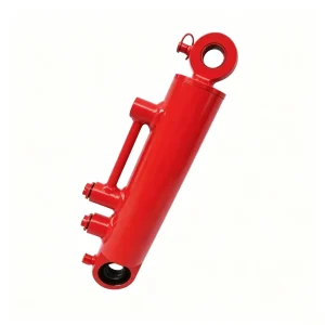
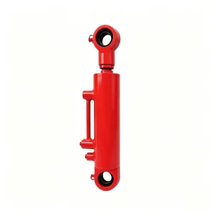
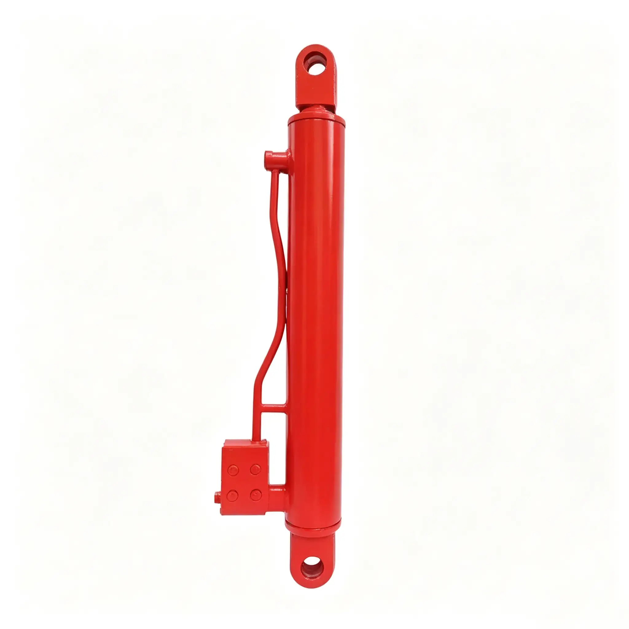
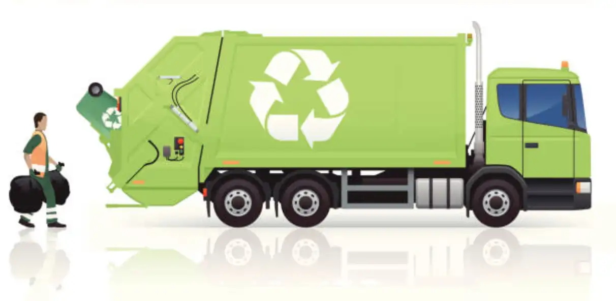
The hydraulic hoist cylinder on a refuse collection vehicle governs the entire body tipping discharge operation. When the vehicle arrives at a transfer station or tipping face, the driver activates the hoist circuit and the cylinder must lift the loaded refuse body — typically weighing 2,000–3,000 kg empty and carrying a waste payload of 4,000–8,000 kg — through a pivot arc of 45–60 degrees to achieve the body angle needed for complete gravity-assisted waste discharge out the open tailgate. The cylinder force required to accomplish this is not constant throughout the stroke: it is highest at the beginning of the lift, when the body’s center of gravity is furthest from the pivot axis and the cylinder is at its least favorable geometric angle, and it decreases progressively as the body approaches vertical.
A 63 mm bore cylinder at 200 bar system pressure generates approximately 62 kN of push force. For a body weighing 2,500 kg empty with a 6,000 kg waste payload and a body pivot point located 1,200 mm from the body’s center of gravity, the initial tilting moment is approximately 100,000 N·m. With a cylinder moment arm — the perpendicular distance from the pivot axis to the cylinder’s line of action — of 1,600–1,800 mm at the start of the stroke, the cylinder must generate 55–62 kN of force to initiate body rotation. The 63 mm bore at 200 bar sits precisely at this threshold, with the system’s pressure relief valve providing a consistent pressure ceiling that prevents structural overload of the body sub-frame mounting if the body fails to rotate freely due to a mechanical obstruction.
The 465 mm stroke is calibrated to achieve the specific tipping angle required for the body design — typically 45–55 degrees of rotation from horizontal. The relationship between stroke and tipping angle depends entirely on the cylinder’s mounting geometry: the 735 mm C-C mounting distance establishes the cylinder’s anchor point relative to the body pivot, and the combination of C-C distance, cylinder stroke, and pivot arm length defines the maximum tipping angle achieved at full extension. These three parameters are interdependent and must be specified together — changing any one of them changes the body’s maximum tipping angle and potentially its ability to fully discharge waste without remainder.
Structural Integrity and Seal Durability in Heavy-Duty Refuse Truck Body Hoist Cylinders for High-Load Outdoor Service
The hoist cylinder operates in one of the most mechanically demanding positions on the refuse vehicle. Mounted beneath the body, it is exposed to: road debris impact from below when the vehicle travels over rough surfaces; body sub-frame vibration transmitted through both mounting pins during transit over potholed urban roads; thermal cycling from cold start through operating temperature on every shift; and direct water exposure during rain and wash-down. The cylinder must maintain its structural integrity and seal condition through this continuous mechanical and environmental loading across a service life that, for well-maintained municipal fleet vehicles, routinely extends to 8–12 years.
The barrel of this hoist cylinder is manufactured from seamless E355 hydraulic tubing — the same material specified for mobile crane and construction equipment cylinders that must handle high-cycle shock loading in outdoor environments. The barrel is cold-drawn rather than hot-rolled, providing tighter wall thickness tolerances and a fine-grained microstructure that resists crack propagation under fatigue loading. Both end caps are full-penetration welded using a controlled heat input process that minimizes heat-affected zone softening adjacent to the weld, and the weld seam is subject to magnetic particle inspection (MPI) on a sampled basis from each production batch to confirm freedom from surface-breaking defects.
The 40 mm rod — giving a rod-to-bore ratio of 0.635 — is sized above what pure axial force calculation would require. The additional rod diameter is specified to handle the bending loads imposed when body tipping geometry is slightly misaligned, or when wind loading acts on the elevated body during discharge on exposed tipping faces. The rod is manufactured from 42CrMo4 alloy steel, heat-treated to tensile strength of 900–1,100 MPa, then precision-ground and hard-chrome plated to 25–30 μm. This alloy grade provides significantly better fatigue resistance compared to the plain C45 steel commonly used in lower-specification cylinders — an important consideration for a cylinder that performs thousands of full-load tipping cycles across its service life.
Maintenance Planning and Replacement Sourcing for Refuse Truck Hoist Cylinders in Municipal and Commercial Fleet Operations
The hoist cylinder is a low-frequency but high-consequence component in the refuse vehicle maintenance program. With 2–6 full tipping cycles per vehicle per shift, the cylinder accumulates relatively few cycles compared to the collection arm or latch cylinders — but each cycle is at or near peak system pressure with the full body and waste payload, meaning the structural and seal loading per cycle is at the high end of the cylinder’s design envelope. This combination of moderate cycle count and high per-cycle loading means the hoist cylinder typically outlasts smaller cylinders in service hours, but its failures are more consequential: a hoist cylinder seal failure at a transfer station grounds the vehicle immediately, as the body cannot be lowered safely for road transit with a leaking or pressure-insufficient hoist circuit.
Fleet maintenance managers should include the hoist cylinder in every major service inspection at 500–750 operating hours, covering: rod surface examination for chrome integrity and scoring; gland nut torque check (vibration during body transit progressively loosens gland nuts that are not secured with thread-locking compound or mechanical retention); pin bore wear measurement at both clevis connections; and hydraulic port fitting condition. A proactive seal replacement at 3,000–5,000 operating hours — or immediately at the first sign of visible rod seal seepage — prevents the more expensive consequence of a field failure requiring a breakdown recovery vehicle and emergency cylinder replacement from stock.
We supply hoist cylinders to municipal waste departments through both open-market and formal tender supply routes, providing the EN 10204 3.1 material certificates, pressure test records, and dimensional inspection reports required by public sector procurement processes. For fleet operations not subject to formal tender requirements, we offer framework supply agreements with committed annual pricing and guaranteed stock allocation — eliminating the price variability and lead time uncertainty of spot-market procurement and supporting the forward planning that effective fleet maintenance budgeting requires. Technical support including installation torque specifications, system pressure verification guidance, and seal rebuild procedures is provided as standard with all supply relationships.
- Rear-load refuse compactor trucks — body tipping at transfer station discharge
- Side-load automated collection vehicles — body hoist sub-frame actuator
- Roll-off container trucks — sub-frame body tipping hoist cylinder
- Bulk organic waste collection vehicles — body tipping for composting facility discharge
- Gully emptier vehicles — tank body hoist for spoil discharge
- Street sweeper trucks — debris hopper tipping cylinder
At 200 bar system pressure, the 63 mm bore generates approximately 62 kN of push force. The actual maximum liftable body weight depends on the cylinder’s mechanical advantage at the start of the tipping stroke — determined by the mounting geometry and the C-C distance relative to the body pivot axis. For typical refuse body hoist geometry with a 735 mm C-C mounting distance, this cylinder is rated for total body plus payload weights up to approximately 9,000–11,000 kg, covering most standard 6–14 cubic meter refuse collection vehicle configurations. Heavier bodies should be evaluated with a specific mounting geometry calculation.
The cylinder itself has no ground slope restriction — it generates hydraulic force regardless of vehicle orientation. However, tipping on sloped ground introduces lateral body moment loads that the mounting pins and sub-frame structure must accommodate. The cylinder’s clevis pin bores are machined to H7 tolerance with hardened steel pins and bronze bushes that handle moderate off-axis loading. For regular operation on significantly sloped tipping faces — more than 5 degrees from horizontal — consult with our engineering team to confirm the mounting pin shear capacity against your specific body dimensions and slope conditions.
Yes. A pilot-operated load-holding valve (counterbalance valve) fitted directly to the cylinder’s cap-end port is available as a factory-fitted option and is strongly recommended for refuse truck hoist applications. This valve prevents the body from lowering due to internal cylinder leak or hydraulic line failure while the body is elevated — a critical safety requirement for OSHA 1910.178 compliance and equivalent EU Machinery Directive safety standards. We strongly advise against relying solely on the directional control valve for load holding in a body tipping application.
Our standard documentation package for tender submissions includes: dimensional drawings to ISO 5457 format, EN 10204 3.1 material certificates for barrel tubing and rod stock, hydraulic pressure test records (tested at 1.5× rated working pressure per batch), seal compound data sheets including temperature range and fluid compatibility, and a copy of our ISO 9001:2015 certification scope. Additional documentation including FMEA summaries and first-article inspection reports can be provided on request for procurement programs requiring enhanced quality evidence.
Procure the Refuse Truck Hoist Cylinder — Certified, Tested, Framework Contracts Available
Request formal quotations with material certification, pressure test documentation, and dimensional drawings for tender submissions. Volume pricing and multi-year supply framework agreements available.