Beschrijving
Hydraulic Cylinders › Boom Swing Cylinders › Compact Excavators
Front Boom Swing Cylinder
for Compact Excavators
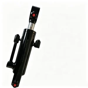
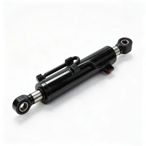
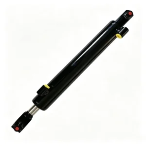
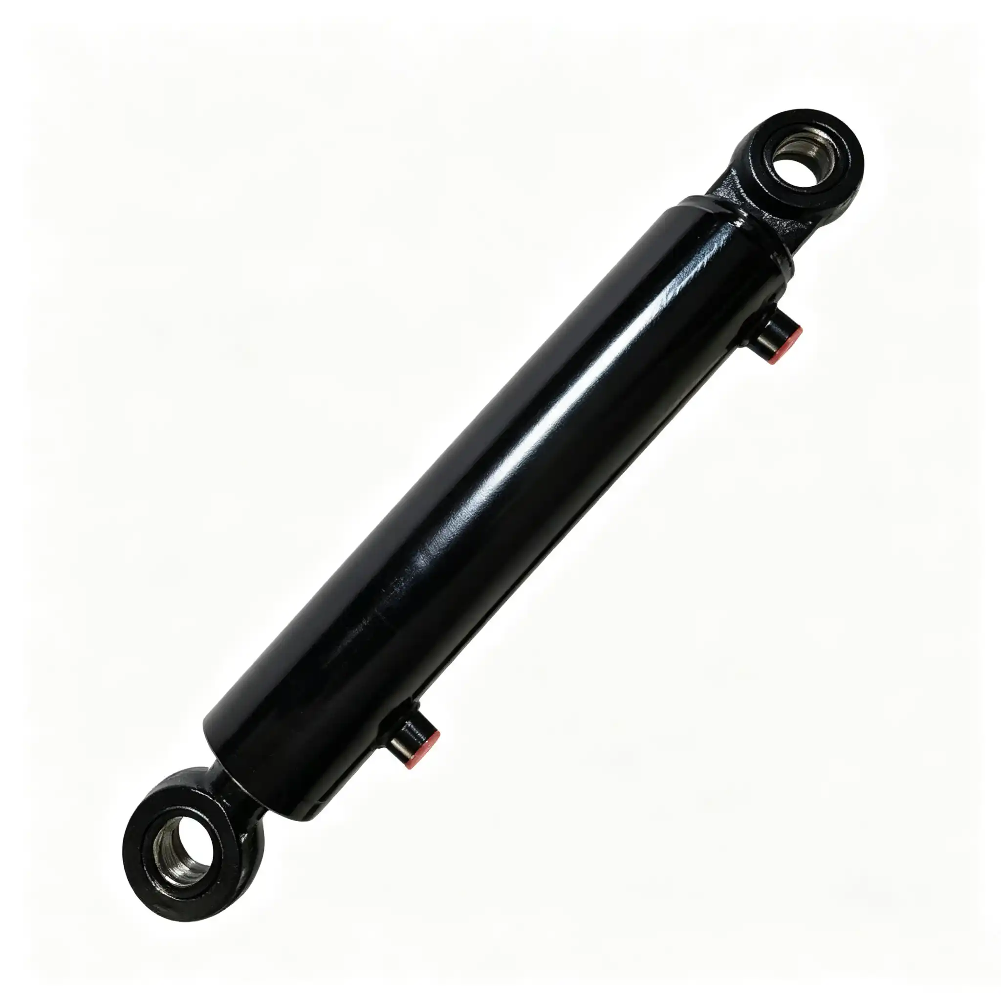
63 mm bore · 35 mm rod · 270 mm stroke · 500 mm installation distance. A front-mounted boom swing cylinder engineered for the combined torque, lateral impulse, and mid-arc force geometry of compact excavator offset digging — built to a structural standard that the weight and inertia of a front swing assembly demand.
Rod: 35 mm
Stroke: 270 mm
Install: 500 mm
Position & Pain Points
Why the Front Boom Swing Cylinder Carries a Heavier Structural Burden Than Any Other Swing Position
The Force Problem
Front-mounted boom swing cylinders sit at the forward end of the machine’s swing frame — the point furthest from the undercarriage centre of gravity. When the boom carries a loaded bucket at full lateral offset, the front swing cylinder must resist the combined overturning moment of the extended attachment mass, not merely the in-plane swing torque. This creates a resultant force at the cylinder’s mounting pins that has both a lateral (swing) component and a vertical (anti-tip) component simultaneously — a combined loading state that rear-frame swing cylinders and all other excavator cylinder positions do not experience.
The Bore Consequence
A 63 mm bore — significantly larger than the 50 mm bore used in the majority of mini excavator swing cylinders — is the direct engineering response to this combined loading. The additional 25% piston area above a 50 mm bore provides the force reserve needed to maintain swing authority and positional control at extreme lateral offset, where mechanical advantage from the pivot arm geometry is at its minimum and where the overturning moment contribution to pin loading is at its maximum. Specifying a 50 mm bore cylinder in this position to save cost produces a machine that hesitates or cannot hold position at full offset under loaded conditions.
The 35 mm rod paired with the 63 mm bore maintains a bore-to-rod ratio of 1.80:1 — a ratio that provides meaningful pull-stroke force on the return swing while keeping the rod’s slenderness ratio within safe structural limits at 270 mm full extension. The 500 mm installation distance places this cylinder in the compact but geometrically demanding space of the front swing frame, where pin alignment accuracy directly governs whether the cylinder operates in pure axial loading or carries parasitic bending from day one of service.
Specification Rationale
63 mm Bore / 35 mm Rod / 270 mm Stroke: Engineering Intent Behind Each Dimension
| Parameter | Value | Mechanical Implication |
|---|---|---|
| Bore | 63 mm | Piston area 31.2 cm². Push force 62.4 kN at 20 MPa — 59% greater than a 50 mm bore, covering the overturning-moment contribution to pin loading at full offset |
| Rod | 35 mm | Annulus area 21.7 cm². Pull force 43.4 kN at 20 MPa. Section modulus 4,209 mm³ — adequate bending resistance for combined axial and lateral front-frame loading |
| Stroke | 270 mm | Generates 70–90° of lateral boom arc through the compact excavator front swing pivot geometry. Matched to the angular range required for wall-proximity and foundation-edge digging without track repositioning |
| Installation | 500 mm | Pin-to-pin retracted length. Sets the neutral boom position. Verify against machine swing-frame pivot spacing before ordering — a 5 mm mismatch pre-loads the pin bushings and imposes a permanent bending bias on the rod from installation day |
| Position | Front Swing | Carries combined in-plane torque and out-of-plane overturning moment. Largest bore in the swing cylinder segment for this machine class |
Push Force
62.4 kN
@ 20 MPa · 63 mm bore
Pull Force
43.4 kN
@ 20 MPa · 35 mm rod
Swing Arc
70–90°
Full lateral range through front pivot geometry
The 63 mm bore’s 62.4 kN push force is not merely about swing speed — it is about force reserve at the end-of-arc position. At maximum lateral offset where the pivot arm and cylinder centreline approach alignment, mechanical efficiency drops to 20–35% of peak. With a 50 mm bore at this position, available swing torque at the pivot may fall below the torque required to hold a loaded 200 kg bucket against the overturning moment contribution from the offset attachment mass. The 63 mm bore maintains positive torque reserve at this critical geometry — which is why the front position carries the larger bore while the rear or side positions on the same machine may use a 50 mm unit.
Manufacturing & Materials
Induction Hardening, Hard Chrome, and Polyurethane Sealing — Specified for a Cylinder That Carries Both Swing Torque and Overturning Load
High-Frequency Induction Hardening
The 35 mm rod is machined from 45# medium-carbon steel (≥ 600 MPa tensile) and induction-hardened to HRC 54–58 at a case depth of 1.5–2.5 mm, with the core remaining at HRC 28–32. For a front swing cylinder under combined axial and overturning loads, this surface-to-core gradient is structurally non-negotiable: the hard surface resists abrasive contact at the rod-seal and guide-bearing interfaces, while the ductile core absorbs the bending-fatigue cycles generated by the out-of-plane force component at every swing reversal. A fully through-hardened rod of the same surface hardness would have significantly reduced notch toughness — it would be brittle at the rod-end thread root under repeated bending loads, a site where fatigue crack initiation would be undetectable until fracture.
Hard Chrome Plating — HV 900+
A 25–40 μm electroplated hard chrome layer achieves HV 900–1,000 surface hardness and is ground to Ra 0.2–0.4 μm after plating. The chrome’s micro-porosity retains a boundary oil film at the rod-seal interface between strokes — critical for a swing cylinder that spends significant time in a fixed position (boom held at offset while the operator works the stick and bucket) and then reverses rapidly. Without a retained oil film, the first stroke after a static hold period generates dry-contact stick-slip at the seal lip, imposing a tearing stress at the lip root that accumulates over thousands of hold-then-swing cycles into premature lip cracking. The 35 mm rod’s larger circumference relative to a 30 mm rod provides a proportionally greater oil-film reservoir in the chrome micro-porosity — an incidental but functionally useful advantage of the larger rod diameter.
Polyurethane Seal Stack — NOK / SKF Grade
The primary rod seal is a polyurethane U-cup of the formulation used in NOK and SKF service kits for the 63 mm bore class. Its self-energising lip geometry increases contact force proportionally with system pressure — providing stronger sealing exactly when the swing cylinder is under maximum load, which is the same moment that internal bypass would be most operationally consequential. The piston seal uses a step-cut PTFE or polyurethane U-cup configuration that resists micro-extrusion into the piston-barrel clearance under the hydraulic pressure spikes generated at end-of-stroke reversal. A backup ring in a dovetail groove behind the primary rod seal captures any transient bypass from cushion pressure events, preventing momentary spikes from appearing as external leakage at the rod gland.
- Guide rings: Fibre-reinforced PTFE bands at piston and rod guide positions absorb the lateral load component from the overturning moment without metal-to-barrel contact — protecting bore surface finish in a position where lateral rod loading is higher than on any other cylinder position on the machine.
- End-cap weld integrity: Stress-relief heat treatment after barrel-to-end-cap welding reduces residual tensile stress in the heat-affected zone from 200–350 MPa (as-welded) to 50–100 MPa — extending fatigue life under the combined axial and lateral cyclic loading profile of front swing service.
- Static O-ring seals: High-ACN nitrile (≥ 70% acrylonitrile content) O-rings at all static gland interfaces resist mineral hydraulic oil degradation and maintain compression set integrity at operating temperatures up to 80°C sustained during high-intensity confined-site work.
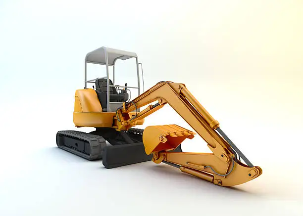
Confined-site front swing operation: where combined swing torque and overturning moment peak simultaneously — the loading condition that defines this cylinder’s 63 mm bore specification
Force & Structural Analysis
Overturning Moment, Mid-Arc Lateral Loading, and End-of-Stroke Impulse: Three Structural Demands Unique to Front Swing Position
1 — Overturning Moment at the Front Pivot Pin
When a compact excavator holds its boom at 60° lateral offset with a loaded bucket — a standard position for lifting spoil into a skip on a confined site — the attachment mass (boom + stick + bucket + material, typically 180–320 kg combined) acts through a horizontal moment arm relative to the front swing pivot. At 1.2 m horizontal distance from the pivot to the bucket centre of mass, a 250 kg total attachment mass generates an overturning moment of approximately 2.94 kN·m at the swing pivot pin. This moment is reacted by a vertical force couple at the cylinder’s top and bottom pin mounting points. At 300 mm between the cylinder’s pin bores in the swing frame, the vertical reaction force at each pin is approximately 9.8 kN — a load acting perpendicular to the cylinder’s centreline, bending the rod and loading the barrel mounts vertically in addition to the in-plane swing force the cylinder is simultaneously generating. No other cylinder position on a compact excavator carries this superimposed vertical reaction load during normal productive operation.
2 — Torque Dead-Zone and Why 63 mm Bore Is the Minimum for This Position
At maximum lateral offset — where the boom swing cylinder pivot arm approaches alignment with the cylinder centreline — the swing torque mechanical advantage drops to 20–30% of its mid-arc peak. Through a typical front swing pivot arm of 220 mm, the maximum available swing torque from the 63 mm bore cylinder is 62.4 kN × 0.22 m = 13.7 kN·m at peak efficiency (90° geometry). At the end-of-arc position at 25% efficiency, available torque is approximately 3.4 kN·m. This is the minimum torque the machine must have to hold the boom against the overturning moment (2.94 kN·m calculated above) plus any residual soil friction or weight-transfer effects — with only 16% torque margin. A 50 mm bore cylinder at the same position would deliver 39.3 × 0.22 × 0.25 = 2.16 kN·m — insufficient to hold the boom against the overturning moment alone, without any swing friction. This is the force-path logic that mandates the 63 mm bore for front swing positions as opposed to the 50 mm bore used in less structurally demanding swing locations.
3 — End-of-Stroke Cushioning Under Combined Loading
When the front swing cylinder reaches its stroke limit with the boom carrying a loaded bucket, the hydraulic end-cushion must decelerate not only the in-plane swing momentum but also the vertical oscillation component introduced by the overturning moment’s effect on the suspension geometry of the boom pivot system. A cushion sized only for in-plane kinetic energy absorption will produce a clean deceleration in the swing plane but allow a residual vertical bounce at the boom pivot — transmitted back through the cylinder as a short-burst axial impulse after the main cushion event has ended. The CSYG front swing cylinder end-cap cushion geometry is sized for the combined kinetic energy of the swing inertia and the vertical moment arm oscillation, reducing peak transient pressure from potential 40–65 MPa events to the 22–30 MPa range that standard hydraulic circuit components can sustain without fatigue damage.
Installation & Maintenance
Fitment Verification, Commissioning, and a Maintenance Protocol Calibrated to Front Swing Structural Demands
Pre-Installation: Three Checks Before the First Bolt Is Tightened
Confirm the swing frame pivot spacing matches 500 mm pin-to-pin with the boom at its intended neutral position. Measure both the swing-frame-end and boom-end pin bore diameters and confirm concentricity of the bores — a swing frame that has been bent by a previous impact event often shows a measurable angle between the two pin bores that will impose a permanent torsional pre-load on the new cylinder from the first swing. Inspect both clevis pins for ovality; replace any pin where measured ovality exceeds 0.25 mm before installing the new cylinder to avoid transferring impact damage to the new unit’s clevis bores.
Post-Installation: Cushion Setting and Initial Operational Check
With the machine at operating temperature and the intended working attachment fitted, execute 5 full-speed swings to each stroke limit. Listen for hydraulic hammer at the stop — any audible knock indicates the cushion is undertightened relative to the attachment inertia. Advance the cushion needle valve by half-turn increments until the end-of-stroke deceleration is smooth and silent. Because front swing cylinders carry a heavier boom assembly than rear or side positions, the cushion setting will typically require more restriction than equivalent stroke-length cylinders in other positions on the same machine.
Maintenance Schedule
- Daily: With the boom held at full lateral offset and controls released, observe lateral drift over 90 seconds. Any measurable drift indicates piston seal bypass — at full offset this is a load-holding failure condition, not merely a performance inconvenience, and requires immediate assessment before the next loaded operating shift.
- 50-hour interval: Grease both front swing pivot pins with NLGI #2 EP lithium grease. Front swing pins carry the combined swing force and overturning reaction — they dry out faster under combined loading than rear swing pins, and dry pivot bushings allow the angular play that imposes bending on the cylinder rod at every swing reversal.
- 200-hour interval: Visually inspect the cylinder barrel mounting hardware and swing frame pivot brackets for crack indications, particularly at weld toes and bracket-to-frame interfaces. Front swing frames are subjected to the highest cyclic stress in the machine’s boom support structure — crack detection at 200 hours catches initiation before propagation reaches a structurally significant length.
- 500-hour interval: Replace the wiper seal and primary rod seal as a set. Check the cushion spigot-to-bore clearance at reseal; cushion spigot wear increases the clearance and reduces cushion effectiveness, allowing higher peak pressures at end-of-stroke that accelerate fatigue of the end-cap weld.
- After any overload or tipping event: Inspect the rod for straightness before returning to service. A machine that tips or is caught by a sudden soil collapse applies a large lateral impulse to the front swing cylinder that can permanently deflect a rod whose chrome surface is already compromised. Replace a bent rod immediately — operating with a deflected rod in a position that carries both axial and overturning loads reduces the structural safety margins to unacceptable levels.

Loaded offset hold: the combined swing torque and overturning moment condition that demands a 63 mm bore front swing cylinder where a 50 mm unit would fall short of positional authority
B2B Procurement
Request a Quote, Technical Drawing, or Volume Pricing
Our engineering team holds full dimensional drawings, cushion specification data, overturning moment compatibility tables, and seal-kit breakdowns for this front boom swing cylinder and 2,000+ related compact excavator cylinder variants.
Provide machine model, swing frame pivot spacing, quantity, and destination port. FOB/CIF pricing within one business day.
Material test reports, rod straightness records, weld inspection reports, and certificates of conformance available for OEM and fleet accounts on request.