Beschrijving
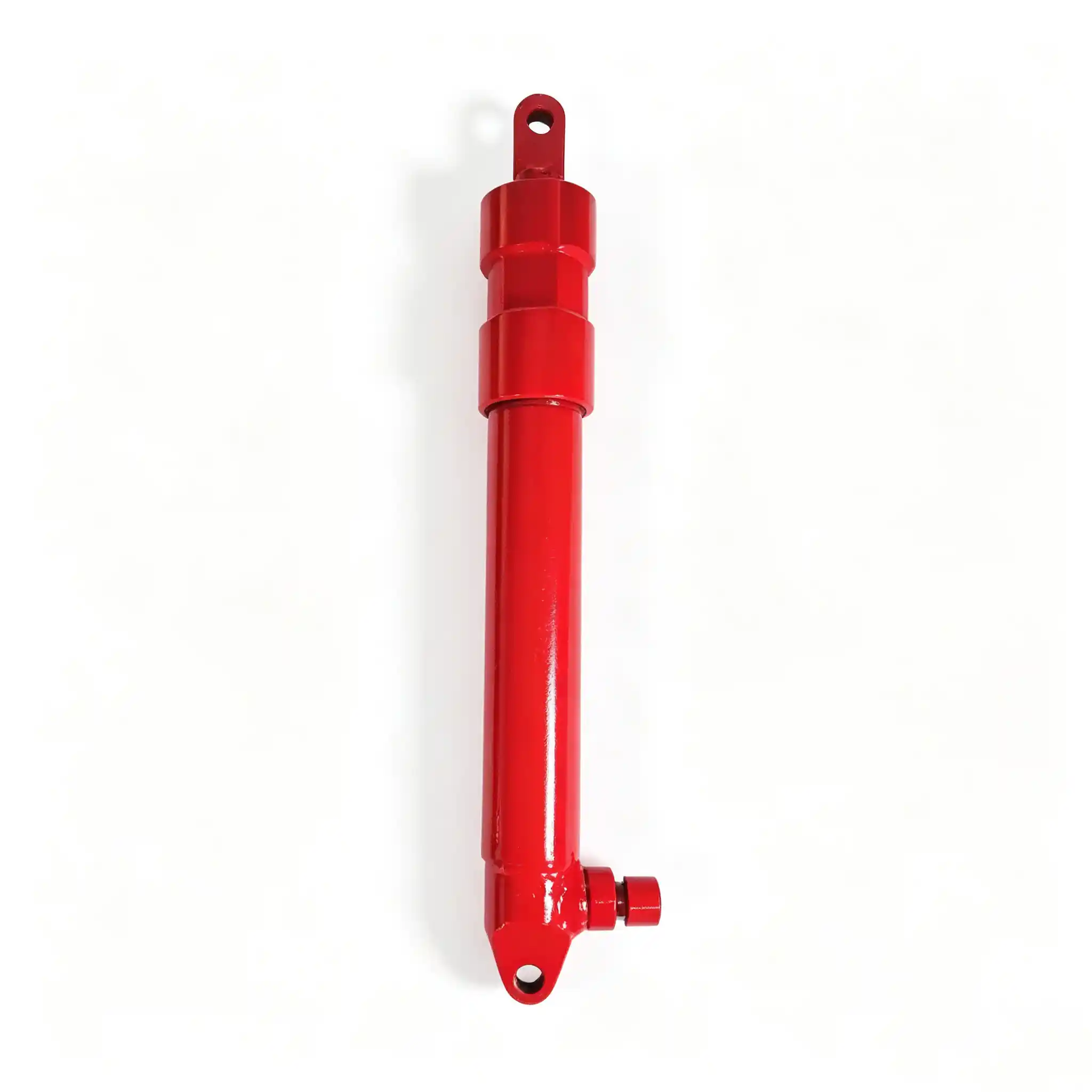
Model: YD25-001A
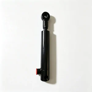
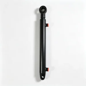
YD25-001A Combine Reel Lift Cylinder
The reel lift cylinder on a combine harvester governs the height of the crop reel — the rotating bat mechanism that guides standing grain into the cutter bar. The YD25-001A achieves this with a compact 30 mm bore, 25 mm rod, and a 235 mm stroke across a 415 mm closed length, placing maximum mechanical precision where it matters most: at the front of the header, in direct contact with the crop.
Belangrijkste specificaties
Rod Diameter25 mm
Stroke235 mm
Mounting Length415 mm
Hydraulic Cylinder for Combine Harvester Reel Adjustment: What the YD25-001A Controls
The crop reel is one of the most agronomically sensitive adjustments on a combine header. Set it too high and lodged or leaning grain passes under the bats without being guided to the cutter bar — grain loss at the front of the machine. Set it too low and the bats beat the crop aggressively, causing grain to shatter before it reaches the thresher — another source of harvest loss and crop quality degradation. Getting reel height right, and adjusting it continuously as crop stand conditions change across a field, is a task the operator performs dozens of times per hour on variable terrain or in mixed-yield crop conditions.
The YD25-001A is the hydraulic actuator that makes this adjustment possible on the move, without the operator leaving the cab. Its 235 mm stroke provides the full height travel envelope required by the reel support arm geometry on the target combine platforms — enough vertical range to optimise reel position from short, erect cereal crops to long-strawed or partially lodged crops without mechanical stop adjustments.
Unlike the header lift cylinders in the same machine’s hydraulic circuit, the reel cylinder is a lower-force, longer-stroke actuator. The reel itself — typically a fabricated tube-and-bat assembly running 4–6 m across the header width — is counterbalanced by its own weight distribution and by the reel drive mechanism, so the net cylinder load is primarily the imbalance force plus drag from the reel bearing pivot arms. A 30 mm bore is well-suited to this load profile, delivering approximately 1,060 N push force at 150 bar — sufficient for reel positioning without over-pressurising the lightweight reel support structure.
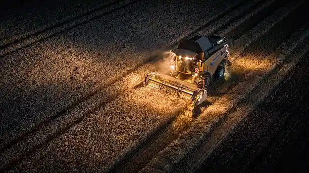
Reel height control is a continuous in-operation adjustment — the YD25-001A must respond precisely across its full 235 mm stroke range.
YD25-001A Combine Reel Lift Cylinder Specifications: Engineering Rationale Behind the Numbers
The YD25-001A’s dimensional configuration — particularly the 25/30 rod-to-bore ratio of 83% — reflects the specific mechanical demands of reel actuation:
- Bore Ø 30 mm / Force Output: The 30 mm bore produces a push-side piston area of approximately 7.07 cm². At standard combine hydraulic pressures of 120–160 bar, this delivers 848–1,131 N of push force. This is sized specifically for reel weight and drag loads — using a larger bore would create a force mismatch that makes precise positioning difficult because small valve movements would produce large position steps.
- Rod Ø 25 mm (83% ratio): The thick rod relative to bore diameter means the pull force (retract, lowering the reel) approaches the push force closely. This symmetry is important for smooth reel lowering control — a thin rod would produce a large force differential that makes lowering feel abrupt compared to raising, a phenomenon operators notice and dislike in working conditions where they are making constant incremental adjustments.
- Stroke 235 mm: The longest stroke in the small-cylinder category of combine hydraulics. 235 mm of travel enables the reel arm pivot geometry to sweep the full height range — from flush with the cutter bar level for short crops to maximum height for tall, standing grain — in a single continuous cylinder motion without intermediate lockouts.
- Closed Length 415 mm: The reel support arm mounting geometry on target platforms requires a cylinder that is physically 415 mm between pin centres in the retracted state. This dimension determines the geometry of the reel’s lowest position and must be matched precisely to ensure that the arm does not bottom out mechanically before the cylinder reaches full retract.
Together, these specifications describe a cylinder that is not just a force producer but a proportional positioning device — one where the mechanical design actively supports smooth, controllable reel movement across its full travel range.
Construction Detail: Sealing and Surface Finish for Long-Stroke Reel Service
The 235 mm stroke on a 30 mm bore cylinder puts particular demands on the rod seal system. At full extension, the rod extends 235 mm beyond the gland — a significant cantilever length relative to the bore size. Any deflection in the reel support arm under asymmetric crop loading transfers a side-load component to the rod at the gland, which the rod seal must accommodate without extrusion or rapid wear. For this reason, the YD25-001A uses a guide ring ahead of the primary rod seal that absorbs lateral load before it reaches the seal lip contact zone.
The chrome-plated rod surface on the YD25-001A meets a minimum hardness of 850 HV with chrome thickness ≥ 20 µm. The combination of hard chrome and a correctly dimensioned rod guide ring allows this cylinder to tolerate the side-loading conditions typical of reel cylinders on headers that are not perfectly aligned — a common real-world condition in headers that have suffered field impacts or where bracket wear has developed over multiple seasons.
The barrel bore is honed to Ra ≤ 0.4 µm, compatible with the polyurethane piston seal specified for this model. PU seals are preferred in reel cylinder applications because the slow, proportional movements of reel positioning expose the seal to boundary lubrication conditions more often than the intermittent full-cycle movements of header lift cylinders. In boundary lubrication, PU outperforms NBR in both friction stability and resistance to extrusion into the clearance gap between piston and bore wall.
End clevis machining meets H7 tolerance on pin bore diameter, with a recommended pin hardness of HRC 40–45 for the mounting pins to minimise pin wear over the many positioning cycles the reel cylinder accumulates in a single harvest season.
Sourcing the YD25-001A: Replacement Guidance and Cross-Reference for Combine Reel Hydraulic Cylinder Parts
Because reel cylinder failures are often gradual — beginning as slow hydraulic drift that causes the reel to drop progressively during operation — operators sometimes run the machine through an extended period of manual reel height adjustment before arranging a replacement. This is not recommended: a drifting reel cylinder forces constant operator intervention, increases fatigue, and typically leads to elevated grain loss at the header front because the operator cannot maintain optimal reel height while also managing ground speed and header height simultaneously.
Replacing the YD25-001A at first sign of drift is more economical than operating with degraded performance through a harvest season. The cylinder cost is a fraction of the grain value lost through a single season of sub-optimal reel positioning.
For distributors and dealers sourcing combine reel hydraulic cylinders:
- Confirm pin bore size and clevis configuration against the machine’s original part before ordering — reel cylinder mounts vary between combine generations even within the same manufacturer’s range.
- Specify port thread standard (BSP, NPT, or metric) based on the hose fittings already on the machine — retrofit adapters create additional leak points.
- For fleet operators running multiple headers, ordering cylinder pairs (left and right reel lift, where dual-cylinder headers are used) ensures matched hydraulic response on both sides of the header.
We can supply the YD25-001A as a direct OEM-equivalent replacement or in custom configurations where a specific combine platform requires modified clevis geometry, port location, or protective coating for high-humidity rice harvest environments.
Complete Technical Specifications
| Parameter | Value |
|---|---|
| Model Number | YD25-001A |
| Product Type | Reel Lift Cylinder (拔禾轮油缸) |
| Bore Diameter | 30 mm |
| Rod Diameter | 25 mm |
| Stroke | 235 mm |
| Closed Length (C–C) | 415 mm |
| Rod-to-Bore Ratio | 83% |
| Cylinder Type | Double-acting |
| Seal Material | Polyurethane (PU) + guide ring + dust wiper |
| Rod Surface | Hard chrome plated, ≥20 µm, 850 HV min. |
| Sollicitatie | Combine reel height adjustment / reel lift arm |
| MOQ | 1 pc (sample); stock orders from 10 pcs; pair orders available |
Request YD25-001A Pricing or Cross-Reference
Supplying this combine reel lift cylinder to distributors, repair workshops, and fleet operators across global grain-growing markets. Contact us with your quantity, platform detail, or OEM part number for a same-day response on pricing, availability, and technical documentation.