Beschrijving
YM4P.83.01 · Corn Harvester Series
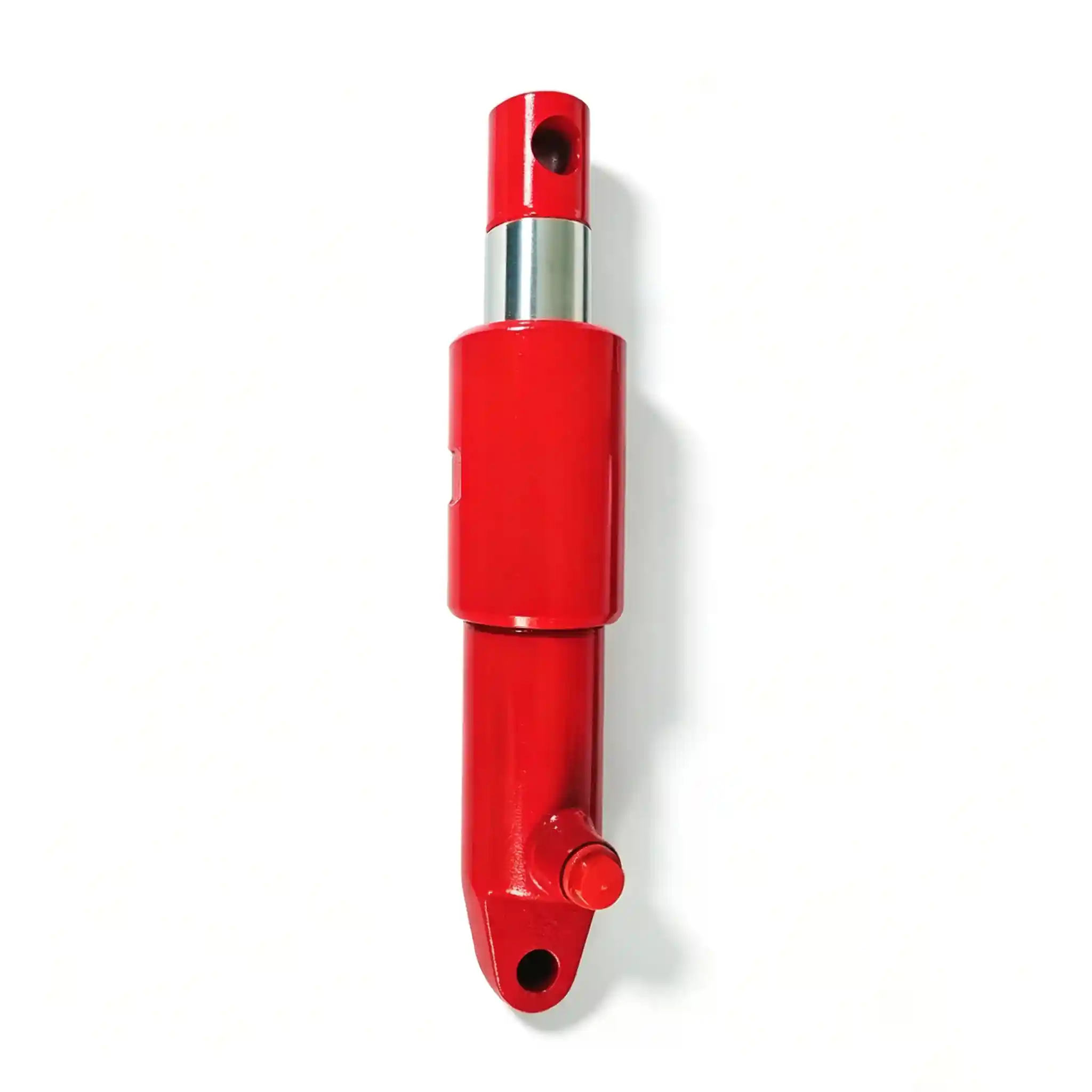
Corn Harvester Chopper Cylinder
High-force, short-stroke actuator for stalk chopper gap adjustment and blade-engagement mechanisms on 4-row corn harvesters.
Bore 56 mm
Rod 50 mm
Stroke 130 mm
C/C 390 mm
Part No. YM4P.83.01
Full Specification at a Glance
Bore Diameter
56 mm
Push force ≈ 39.4 kN @ 160 bar
Rod Diameter
50 mm
Rod/bore ratio 0.893 — structural specification
Stroke
130 mm
Covers full chopper gap adjustment range
Mounting Distance
390 mm
C/C retracted — OEM bracket-match dimension
Rated Pressure
160 bar
Continuous working pressure
Surge Pressure
250 bar
Blade-strike shock rating — proof-tested
Rod Chrome
25–30 µm
Hard chrome HV 800+, full rod length
Seal System
PU / PTFE
Quad-ring piston, −25 °C to +100 °C
Port Standard
BSP G3/8″
SAE ORB available on request
Mounting Style
Clevis × 2
Ø20 mm pin bore both ends
Push Force (Extend)
39.4 kN
F = 160 bar × π/4 × 56²
Pull Force (Retract)
8.7 kN
F = 160 bar × π/4 × (56²−50²)
Push / Pull Ratio
4.53 : 1
Chopper engagement demands high push force; spring-return handles retract — this ratio is deliberate, not a compromise.

The chopper system runs continuously during harvest — its hydraulic actuator must hold position against blade-strike vibration for hours at a stretch
Corn Harvester Chopper Cylinder 56mm Bore 50mm Rod — Why This Specification Exists and What Happens When It Is Wrong
Q
Why does a 130 mm stroke chopper cylinder need a 50 mm rod — the same diameter as the 300 mm stroke header lift cylinder?
Stroke length does not determine rod diameter — load case does. The chopper cylinder operates in a sustained high-vibration environment: the rotating blade shaft runs at 1,200–1,800 RPM directly adjacent to the cylinder mounting bracket, and blade-on-stalk impacts generate repeating impulsive lateral loads through the chopper frame into the cylinder pivot. A slender rod on a short-stroke cylinder in this position will develop fretting wear at the piston seal and gland under these lateral micro-cycles, not under conventional push-pull loading. The 50 mm rod provides the lateral bending stiffness to prevent rod deflection amplitudes that would accelerate seal fretting — a failure mode that a buckling calculation alone will not reveal because it is fatigue-driven, not static.
Q
The push/pull ratio is 4.53:1 — isn’t that an extreme asymmetry? What does it mean in practice?
It is extreme for a positioning cylinder, but it is correct for a chopper engagement actuator. Here is the mechanism: the cylinder pushes the chopper counter-knife mounting rail against its operating spring preload to set blade-to-counter-knife clearance. This requires 39.4 kN because you are compressing multiple return springs simultaneously while overcoming friction in the adjustment rail guides. Once the position is set, the cylinder holds — it is not continuously cycling. When the operator releases or opens the gap, the spring system provides the retract force — the hydraulic pull of 8.7 kN simply controls the rate of retraction, it does not need to overcome the spring alone.
Trying to use a standard 56/32 mm rod cylinder here — which would give a push/pull ratio closer to 1.75:1 and only 22.5 kN push force — would result in the cylinder being unable to compress the counter-knife spring system to the minimum clearance position. The machine would appear to operate but with an excessive blade-to-counter-knife gap, leading to poor stalk chopping quality and elevated whole-stalk rejection rate.
Q
The surge pressure rating is 250 bar — what is causing pressure surges on a position-holding cylinder?
Blade strikes. When a corn stalk contains a buried stone, an embedded metal fragment from previous tillage, or a dense knot section, the rotating chopper blade impacts it with an energy spike that transmits directly through the blade shaft and frame into the counter-knife mounting. If the counter-knife is hydraulically positioned, that impact energy partially translates into a hydraulic pressure spike in the rod-side circuit. On a short-stroke, high-bore cylinder, the hydraulic stiffness (pressure rise per unit displacement) is very high — a 2 mm rod-side displacement at 50 mm rod, 130 mm stroke generates a pressure spike of several tens of bar above circuit pressure. The 250 bar surge rating is not theoretical headroom: it is the calculated peak from a stone-strike event modelled against the circuit’s relief valve response time. Any cylinder rated below 200 bar surge on this position is inadequately specified.
Q
Why is the internal leakage specification tighter here than on the grain tank lift cylinder?
Chopper blade-to-counter-knife clearance is typically set within a range of 1–5 mm. The operational consequence of exceeding the upper limit by even 2 mm is measurable: stalk particle length increases, the proportion of whole-stalk carryover to the field rises, and in markets where straw quality matters for subsequent soil incorporation, agronomic performance degrades visibly. An internal leakage rate above 5 cc/min on the rod-side port of this cylinder translates to approximately 0.3 mm/min gap increase under the counter-knife spring load. Over a 30-minute field section without readjustment, that is a 9 mm drift — enough to take the machine from optimum to poor chopping quality. The ≤ 3 cc/min specification is tighter because the application demands it, not because it is a standard production specification applied universally.
Stalk Chopper Hydraulic Cylinder — Construction Detail and Material Standards
Cylinder Tube
E355 cold-drawn seamless, honed to Ra ≤ 0.4 µm. Wall 7 mm — calculated for 4:1 yield safety at 250 bar. External: zinc phosphate + PU topcoat, 500-hour salt spray.
Chrome Rod
Ck45 steel, ground Ra ≤ 0.2 µm. Hard chrome 25–30 µm, HV 800+. Post-plate ground to h6. At 50 mm Ø, I = 307,000 mm⁴ — lateral stiffness that matters in high-vibration mounting positions.
Piston & Seals
Cast iron piston, double PTFE guide rings. Primary seal: PU quad-ring + PTFE backup. Rod seal: dual-lip PU. Wiper: PU with steel exclusion lip. Full seal kit available separately as catalogued spare.
End Fixings
Clevis both ends, Ø20 mm pin bore, sintered bronze self-lubricating bush. Grease nipple at each pivot. Clevis wall 14 mm machined steel — rated for lateral bending moments from vibration loading.
QC Protocol
Hydrostatic proof test 250 bar × 60 s per unit. Full-stroke cycle × 5 under rated load. Leakage check both ports. Dimensional audit: C/C, stroke, pin bore. Records retained per batch.

Chopper quality — stalk particle size and uniformity — is directly determined by the blade gap the hydraulic cylinder holds
Platform Fit and Fitment Verification
The YM4P.83.01 is OEM-specified for the YM4P 4-row corn harvester chopper mechanism. For distributors cross-referencing this part against other platforms, the following dimensional checks govern correct fitment:
C/C Retracted
390 mm
Primary bracket-match dimension. Measure existing cylinder before ordering.
Pin Bore
Ø20 mm
Both clevis eyes. Verify pin diameter on machine before ordering.
Rod Diameter
50 mm
Do not substitute a thinner rod — see engineering rationale above.
Port Thread
BSP G3/8″
SAE ORB available; specify at order.
Stroke
130 mm
Custom strokes 100–160 mm available on inquiry.
Stalk Chopper Blade Gap Hydraulic Cylinder — Custom Configurations for OEM Integrators
Standard YM4P.83.01 is stocked for direct replacement supply. OEM integrators developing platform-specific chopper mechanisms can specify the following without tooling surcharge at qualifying order volumes:
- Stroke: 100–160 mm within current envelope; adjusted C/C follows accordingly.
- Rod end style: Clevis, knuckle joint, spherical rod eye, or threaded male rod end (M36×2 or to customer drawing).
- Port thread and position: BSP, SAE ORB, NPT, BSPT; side-entry or end-entry port position to suit routing constraints.
- Seal material: Standard PU/PTFE; FKM for HETG/biodegradable fluid circuits; NBR for cost-optimised sealed-environment applications.
- Surface finish: Standard zinc phosphate + PU coat; black oxide; customer-specified paint code.
- OEM marking: Part number engraving, private label, custom colour coding. MOQ ≥ 50 pcs per configuration.
2D drawings and STEP files provided for engineering review before production confirmation. Lead time: 7–15 business days ex-works for standard specifications; 20–30 business days for custom configurations.
Get Technical Support or a Procurement Quote
Request CAD Drawings, OEM Pricing, or Chopper Cylinder Custom Engineering
Every OEM enquiry receives a technical response with dimensional drawings and a material specification sheet — not a catalogue page. Our engineering team can review your platform’s chopper mechanism drawings and confirm correct cylinder specification before order.